
[Click on any image to enlarge]
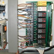
Opto22 PB32HQ relay motherboard overview.
These boards hold
up to eight quad relay modules and a B4 brain board.
Black relays are 120 volt AC outputs.
Yellow relays are 120 volt AC inputs.
Red relays are DC outputs. White relays are DC inputs.
There are four relays in a module. There is a LED indicator
on the top indicating the status of each individual relay (lit
for "on").
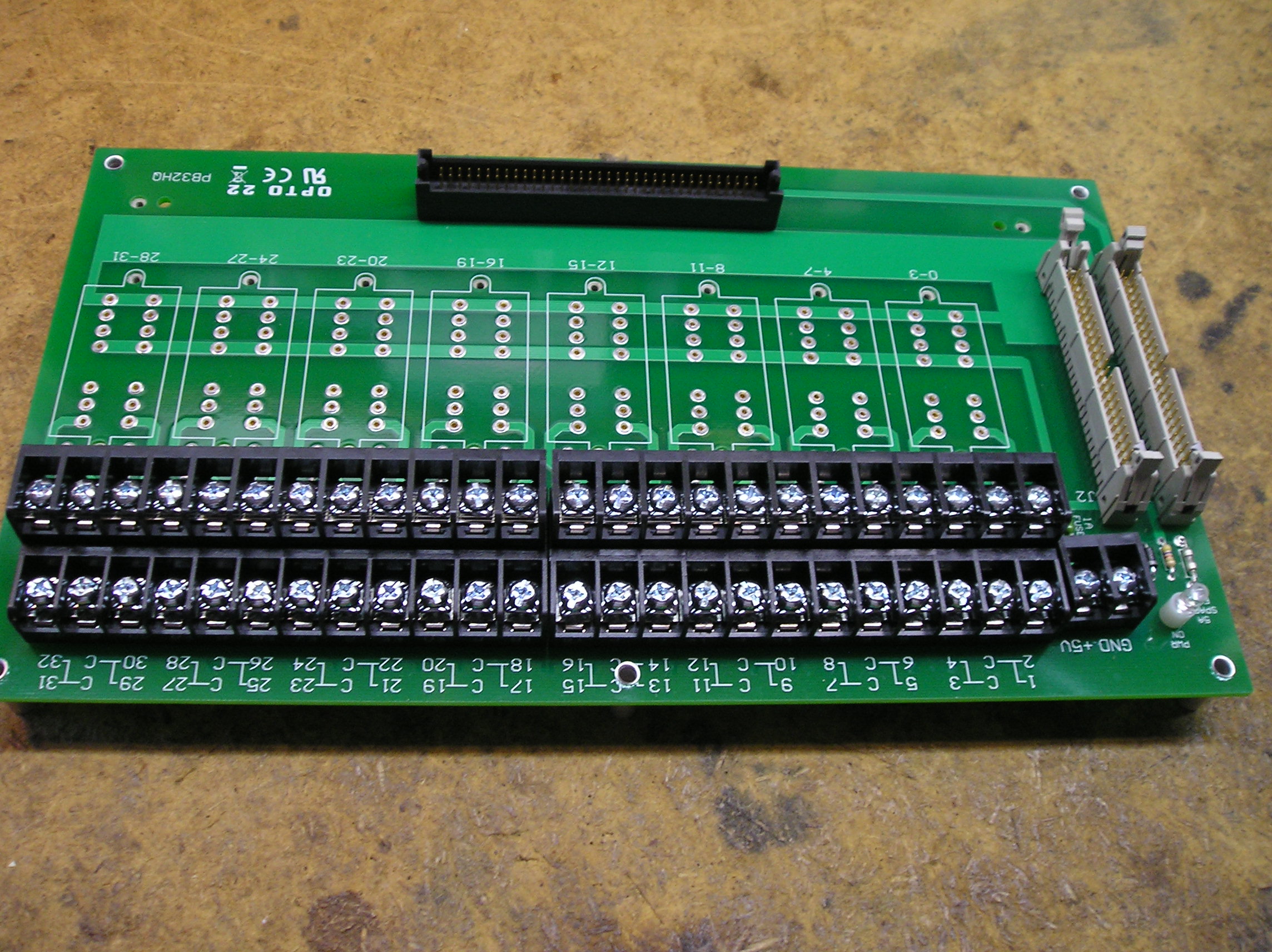
Close-up of the cable connections.
The relay cable plugs
into here. Either another relay cable or a terminator board
plugs into the second socket. Both sockets are identical and
interchangeable.
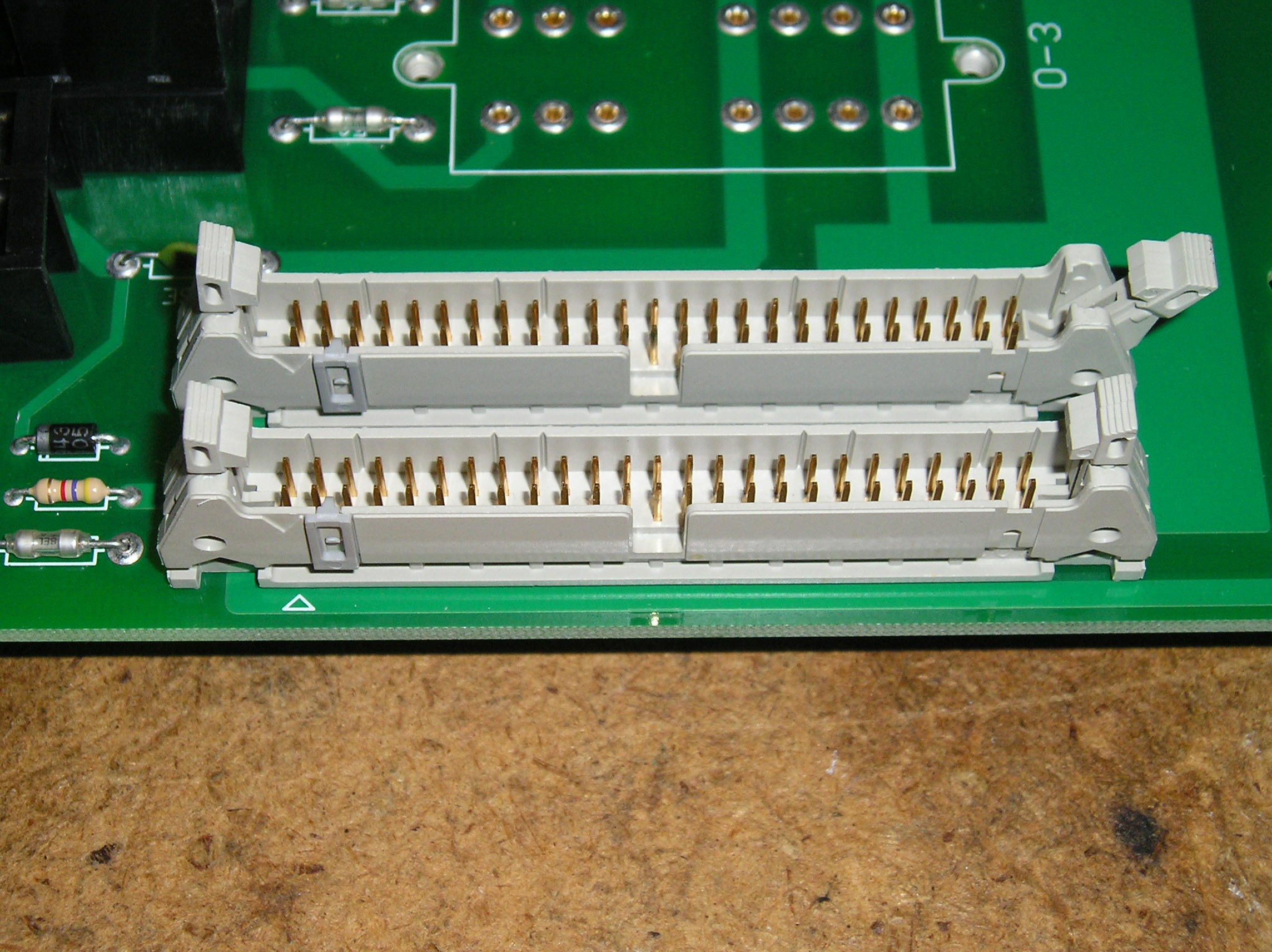
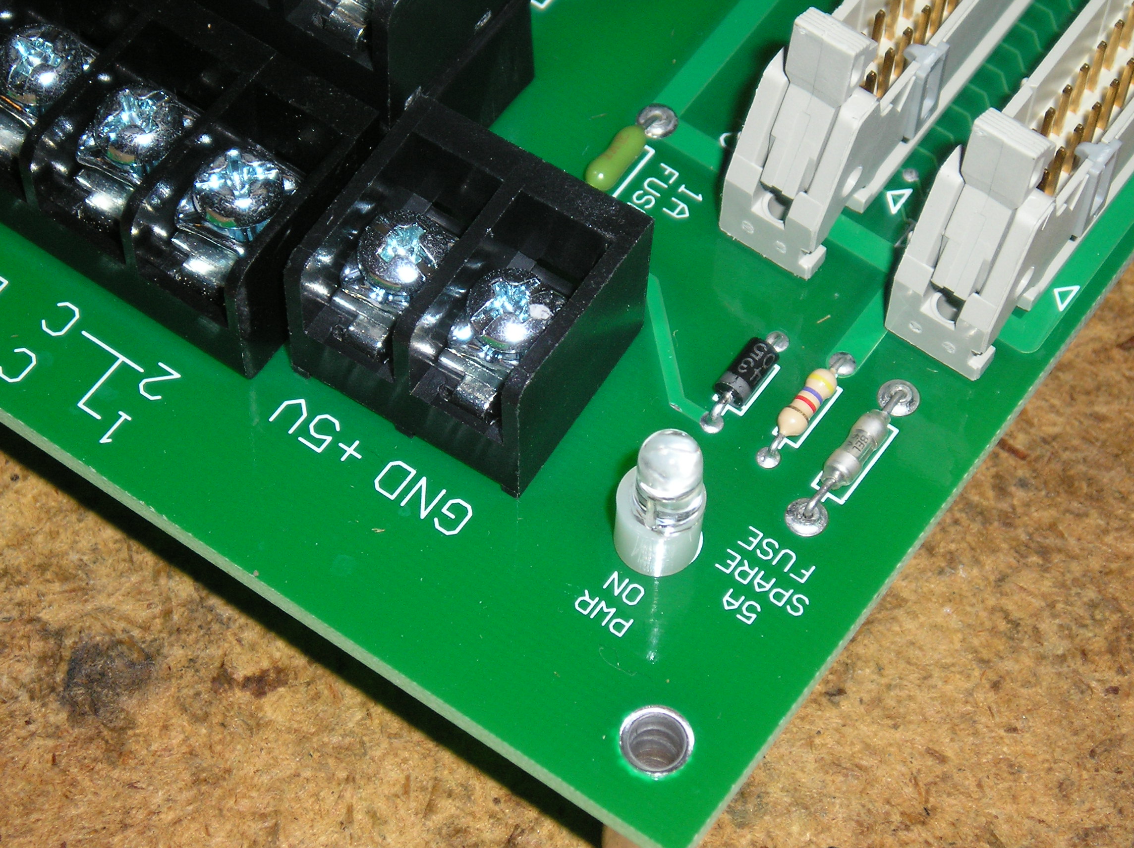
Closeup of where the 5 volts DC power cables connect to the motherboard.
Also note the green 1 amp power fuse (behind the black GND connection block),
the spare 5 amp fuse, and the power LED. The fuses are NOT soldered onto the
board, but unplug by pulling on their leads with needle-nosed pliers.
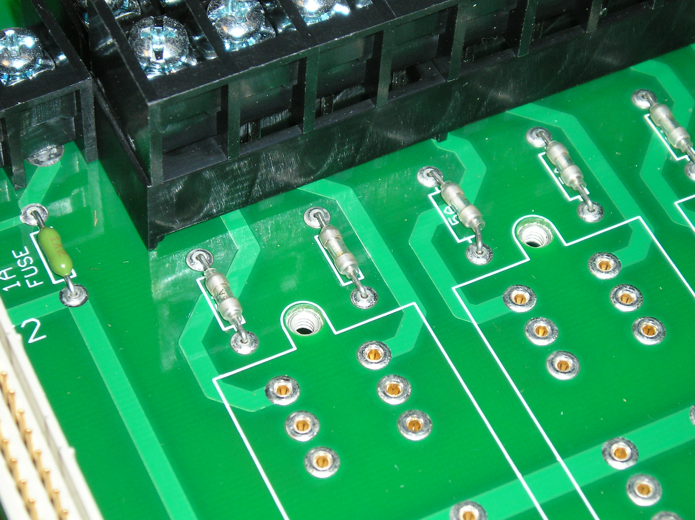
Close-up of the relay fuses.
There are two 5 amp fuses per relay module. The first fuse protects the
first two relays in the module; the second fuse protects the second
two relays in the module.
The fuses are NOT soldered onto the board. They unplug by pulling on their leads with
needle-nosed pliers.
Use 5 amp Littlefuse Pico II fuses (or Buss equiv) as replacements. If your electrical supply
doesn't have (and can't get) any, they're available from Opto22.
See
Link
for more info.
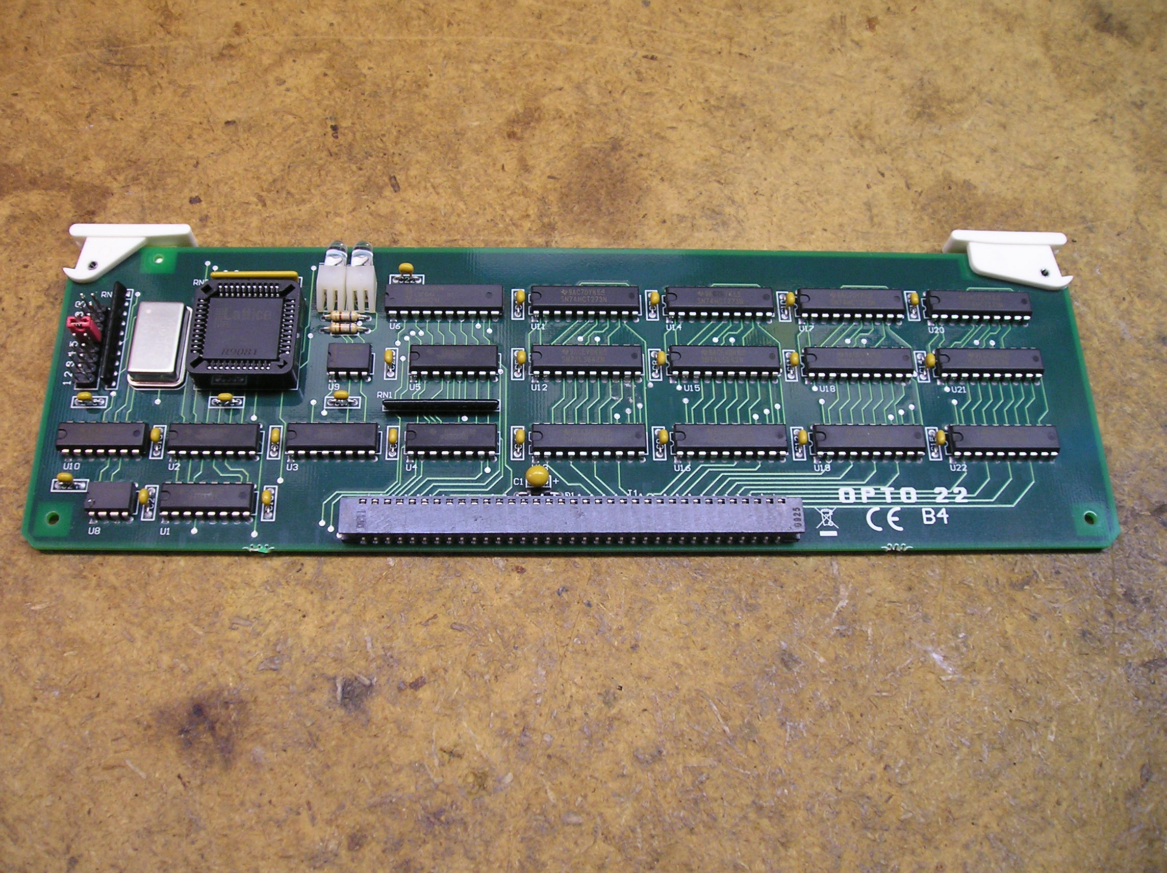
Opto22 B4 Brain board overview.
These boards plug into the relay motherboard
along side of the relay modules.
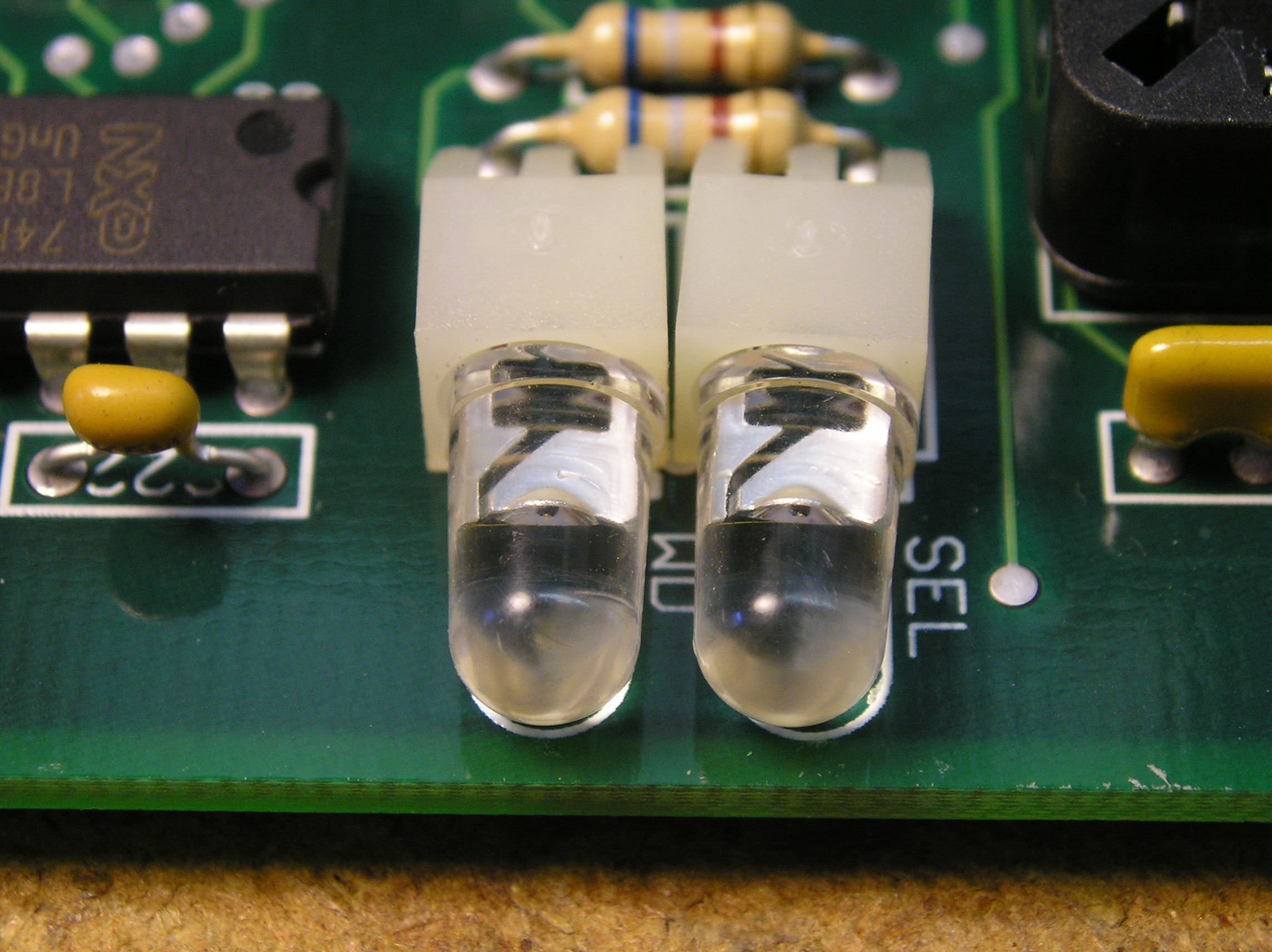
Close-up of the indicator lights.
The "SEL" (select) light blinks when the computer is talking to this control board.
The "WD" (watchdog) light illuminates on a communications failure, indicating
a problem.
Close-up of the address configuration jumpers.
There MUST be a jumper in position #5,
and no jumpers in positions #6 through position #8. These jumpers configure the board
action in case of loss of comm with the batcher (all relays "off").
Jumper positions #1 through #4 set the relay board address.
The first board (typically bottom-most, all black relays) is address 0,
the second is address 1, etc.
See the following table for settings.
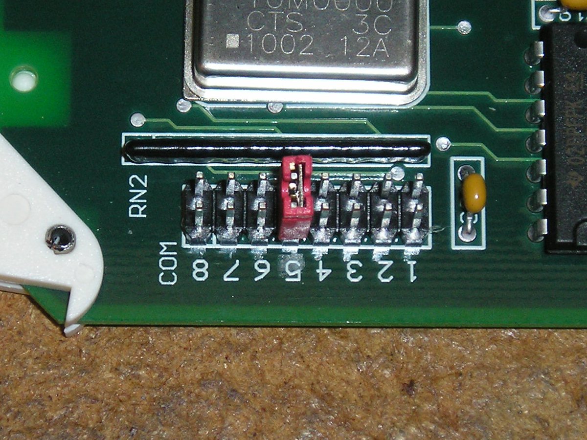
| Board # | Address | #4 | #3 | #2 | #1 |
| 1 | 0 | - | - | - | - |
| 2 | 1 | - | - | - | X |
| 3 | 2 | - | - | X | - |
| 4 | 3 | - | - | X | X |
| 5 | 4 | - | X | - | - |
| 6 | 5 | - | X | - | X |
| 7 | 6 | - | X | X | - |
| 8 | 7 | - | X | X | X |