Use an Arduino to Flicker a Household Light Bulb like a Candle
Weird Flickering Halloween Porch Lights or Pumpkin
[Updated 10/09/20]
This build was inspired by the flickering candelabras in the haunted house attraction at Disneyland. It's an interesting effect, but I thought I could do better. Unlike most lamp flickering designs, this design features a fully programmable table driven dimming sequence. This revised version supports sixteen brightness levels (the previous had only eight). It can optionally suport multiple dimming channels. The final product is used every Halloween, wired into my porch lights.
The engine for this circuit is an Arduino Uno. It is used to drive an optically isolated triac dimming circuit. All of the phase shift timing is done in software.
You will have to build some interface circuitry. You need two circuits (see schematic below):
- A line voltage zero crossing detector, so that the software can establish basic timing.
- One (or more) dimming channels to drive the lighting load(s).
The zero crossing circuit takes the AC power line signal and applies it to the LED diodes of an dual-diode opto-coupler. Resistor R1 limits the peak LED current. The AC voltage keep the LEDs lit except at waveform zero crossing. The output of the opto-coupler keeps the output signal low except at zero crossing time. Resistor R2 provides the pull-up voltage for the output signal. This signal feeds the input of the Arduino.
The lamp driver circuit is a basic phase modulated dimmer circuit. A pulse signal from the Arduino turns on the LED inside the opto-triac chip. Resistor R3 limits the LED current. This signal triggers the internal triac, which then passes 120 vac voltage, current limited by resistor R4, to the gate of a power triac, turning it on. This sends power to the attached light bulb. Note: you may also use a random turn-on type SSR relay module in place of this circuit, but at added cost.
While this build shows only one dimming channel, there is no reason why you couldn't add more channels by adding more lamp driver circuits and expanding the code.
Schematic
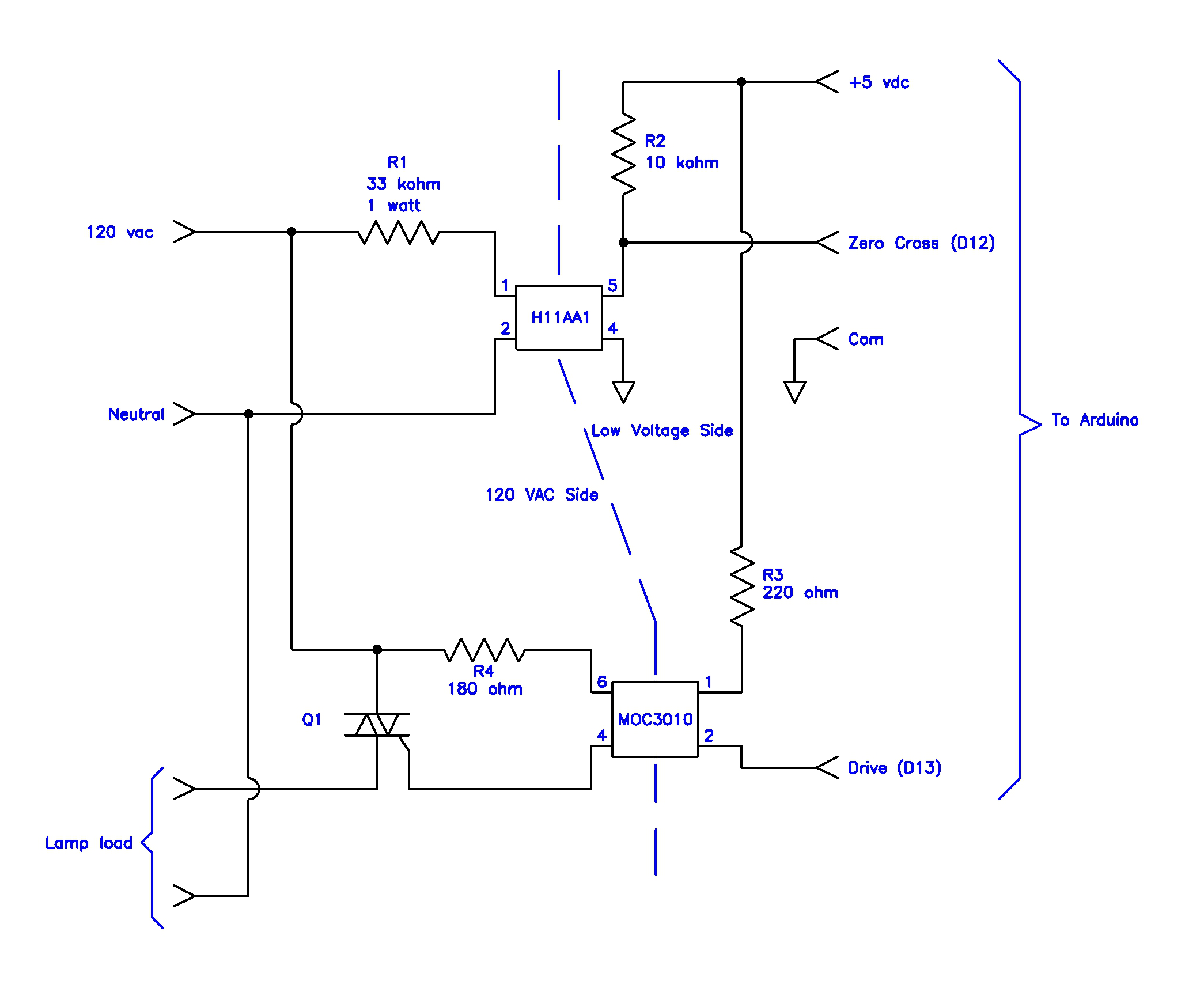
Click on the figure to get a large version.
The Arduino sketch software works as follows:
- The brightness sequence is encoded in the channel_1_table array as an array of sequential brightness values, from 0 (off) to 15 (brightest). The sequence is arbitrary: the one shown in the code was one I liked. You can, obviously, code any sequence you like, of any length. [To make this possible, the tables are stored in program memory instead of normal variable memory, and use a special function to transfer the data between the two.]
- The software waits for an AC line voltage zero crossing event. It then turns off the drive to the lamp driver circuit, loads the next brightness value from the sequence table, and resets a brightness down-counter.
- If the current sequence table brightness value matches the current value of the brightness down-counter, a signal is sent to the lamp driver module, turning the lamp on. If there is no value match, the software delays a half millisecond, decrements the down-counter, and checks again. The amount of delay time from zero-crossing to when the lamp turns on determines the duty cycle of the AC cycle voltage is applied to the lamp. The software continues this "wait and check" logic until the down-counter reaches zero, ending the logic loop. The software then goes back to the step above, waiting for a zero-crossing event.
/*---------------------------------------------
  title: HwMachArduino.ino
    Halloween Machine
  revisions:  4/08/08 - init release
             10/30/08 - port to lugger
              8/14/13 - port to Arduino
             10/01/17 - use PROGMEM
             10/02/17 - 4 bit brightness
             10/08/20 - limit moc3020m drive time

  (c) Telford Dorr 2008-2020

  Permission to use, copy, modify, and/or distribute this software for
  any purpose with or without fee is hereby granted, provided that the
  above copyright notice and this permission notice appear in all copies.

  THE SOFTWARE IS PROVIDED "AS IS" AND THE AUTHOR DISCLAIMS ALL WARRANTIES
  WITH REGARD TO THIS SOFTWARE INCLUDING ALL IMPLIED WARRANTIES OF
  MERCHANTABILITY AND FITNESS. IN NO EVENT SHALL THE AUTHOR  BE LIABLE FOR
  ANY SPECIAL, DIRECT, INDIRECT, OR CONSEQUENTIAL DAMAGES OR ANY DAMAGES
  WHATSOEVER RESULTING FROM LOSS OF USE, DATA OR PROFITS, WHETHER IN AN
  ACTION OF CONTRACT, NEGLIGENCE OR OTHER TORTIOUS ACTION, ARISING OUT OF
  OR IN CONNECTION WITH THE USE OR PERFORMANCE OF THIS SOFTWARE.

  ---------------------------------------------

  This sketch uses an Arduino to flash and dim a
  standard 120 vac incandescent lamp for a flickering
  candle Halloween effect. The entire sequence is
  approximately 56 seconds long, and repeats endlessly.

  The connecting hardware has one controllable
  dimming channel and one zero crossing input
  channel.

  The input port is low except during zero cross.

  The output port is wired up inverted
  polarity - pull down (output = LOW) to activate.

  This software will support multiple lighting channels,
  each with its own brightness sequence table. The
  only caveat is that all sequence tables need to
  be the same length. Add additional I/O and channel
  processing where indicated.

  Eash channel can be controlled to one of sixteen
  brightness levels.

  This is an all-software bit-banging method of
  controlling the channel brightness.

  The main loop controls the basic dimming
  sequence. There is a 'brightness' table for
  each controlled lighting channel. Each table
  value is repeated a specified number of line
  half-cycles (should be an even number) before
  advancing to the next value.

  Table values are fetched, and then the routine
  waits for line voltage zero crossing. Then
  the table values are compared against a
  downcounting counter. When the value matches,
  the appropriate channel is activated, and
  stays activated for the remainder of the line
  half-cycle.

  After each lighting channel is processed, a delay
  routine is called (500 usec). This controls the
  portion of 8.33 msec line half-cycle the
  channel is active, and thus its brightness.

  ---------------------------------------------*/

#include <avr/pgmspace.h>

#define ON LOW
#define OFF HIGH

// Global constants

const uint8_t OUTPORT1 = 13;
// Add more channel port defs here.

const uint8_t STATPORT = 12;
const uint8_t REPEATS = 8;


/*---------------------------------------------
  HW Machine data tables

  Each number represents a 'brightness'
  value. 15 = brightest, 0 = off

  Because this table is large and constant, and
  because we could expand to multiple channels,
  needing miltiple tables, the tables will be
  stored in program memory (hence PROGMEM).
  ---------------------------------------------*/

const uint8_t CHANNEL_1_TABLE[] PROGMEM =
  {
  15, 9,15, 9,13, 9,13, 9,  11, 7,11, 7, 9, 5, 9, 5,     // 1
   7, 3, 7, 3, 7, 3, 7, 3,   9, 5,11, 7,13, 9,15, 9,
  15, 9,13, 9,11, 7, 9, 5,   7, 2, 7, 2, 7, 2, 7, 2,
   9, 5, 9, 5,11, 7,11, 7,  13, 9,13, 9,15, 9,15, 9,

  13, 9,13, 9,11, 7,11, 7,   9, 5, 9, 5, 7, 2, 7, 2,     // 2
   7, 3, 7, 3, 7, 2, 7, 2,   7, 2, 7, 2, 7, 2, 7, 2,
   9, 5, 9, 5,11, 7,11, 7,  12, 9,12, 9,15, 9,15, 9,
  13, 9,13, 9,11, 7,11, 7,   9, 5, 9, 5, 7, 2, 7, 2,

   7, 2, 7, 2, 7, 2, 7, 2,   9, 5,11, 7,13, 9,15, 9,     // 3
  13, 9,11, 7, 9, 5, 7, 2,   9, 5,11, 7,13, 9,15, 9,
  15, 9,15, 9,13, 9,13, 9,  11, 7,11, 7, 9, 5, 9, 5,
   7, 2, 7, 2, 7, 2, 7, 2,   9, 5,11, 7,13, 9,15, 9,

  15, 9,13, 9,11, 7, 9, 5,   7, 2, 7, 2, 7, 2, 7, 2,     // 4
   9, 5, 9, 5,11, 7,11, 7,  13, 9,13, 9,15, 9,15, 9,
  13, 9,13, 9,11, 7,11, 7,   9, 5, 9, 5, 7, 2, 7, 2,
   7, 2, 7, 2, 7, 2, 7, 2,   7, 2, 7, 2, 7, 2, 7, 2,

   9, 5, 9, 5,11, 7,11, 7,  13, 9,13, 9,15, 9,15, 9,     // 5
  13, 9,13, 9,11, 7,11, 7,   9, 5, 9, 5, 7, 2, 7, 2,
   7, 2, 7, 2, 7, 2, 7, 2,   9, 5,11, 7,13, 9,15, 9,
  13, 9,11, 7, 9, 5, 7, 2,   9, 5,11, 7,13, 5,15, 9,

  15, 9,15, 9,13, 9,13, 9,  11, 7,11, 7, 9, 5, 9, 5,     // 6
   7, 2, 7, 2, 7, 2, 7, 2,   9, 5,11, 7,13, 9,15, 9,
  15, 9,13, 9,11, 7, 9, 5,   7, 2, 7, 2, 7, 2, 7, 2,
   9, 5, 9, 5,11, 7,11, 7,  13, 9,13, 9,15, 9,15, 9,

  13, 9,13, 9,15, 7,11, 7,   9, 5, 9, 5, 7, 2, 7, 2,     // 7
   7, 2, 7, 2, 7, 2, 7, 2,   7, 2, 7, 2, 7, 2, 7, 2,
   7, 5, 7, 5, 11, 7,11, 7, 13, 9,13, 9,15, 9,15, 9,
  13, 9,13, 9,11, 7,11, 7,   9, 5, 9, 5, 7, 2, 7, 2,

   7, 2, 7, 2, 7, 2, 7, 2,   9, 5,11, 7,13, 9,15, 9,     // 8
  13, 9,11, 7, 9, 5, 7, 2,   9, 5,11, 7,13, 9,15, 9,
  15, 9,15, 9,13, 9,13, 9,  11, 7,11, 7, 9, 5, 9, 5,
   7, 2, 7, 2, 7, 2, 7, 2,   9, 5,11, 7,13, 9,15, 9,

  15, 9,13, 9,11, 7, 9, 5,   7, 2, 7, 2, 7, 2, 7, 2,     // 9
   9, 5, 9, 5,11, 7,11, 7,  13, 9,13, 9,15, 9,15, 9,
  13, 9,13, 9,11, 7,11, 7,   9, 5, 9, 5, 7, 2, 7, 2,
   7, 2, 7, 2, 7, 2, 7, 2,   7, 2, 7, 2, 7, 2, 7, 2,

   9, 5, 9, 5,11, 7,11, 7,  13, 9,13, 9,15, 9,15, 9,     // 10
  13, 9,13, 9,11, 7,11, 7,   9, 5, 9, 5, 7, 2, 7, 2,
   7, 2, 7, 2, 7, 2, 7, 2,   9, 5,11, 7,13, 9,15, 9,
  13, 9,11, 7, 9, 5, 7, 2,   9, 5,11, 7,13, 9,15, 9,

  15, 9,15, 9,13, 9,13, 9,  11, 7,11, 7, 9, 5, 9, 5,     // 11
   7, 2, 7, 2, 7, 2, 7, 2,   9, 4,11, 7,13, 9,15, 9,
  15, 9,13, 9,11, 7, 9, 5,   7, 2, 7, 2, 7, 2, 7, 2,
   9, 5, 9, 5,11, 7,11, 7,  13, 9,13, 9,15, 9,15, 9,

  13, 9,13, 9,11, 7,11, 7,   9, 5, 9, 5, 7, 2, 7, 2,     // 12
   7, 2, 7, 2, 7, 2, 7, 2,   7, 2, 7, 2, 7, 2, 7, 2,
   9, 5, 9, 5,11, 7,11, 7,  13, 9,13, 9,15, 9,15, 9,
  13, 9,13, 9,11, 7,11, 7,   9, 5, 9, 5, 7, 2, 7, 2,

   7, 2, 7, 2, 7, 2, 7, 2,   9, 5,11, 7,13, 9,15, 9,     // 13
  13, 9,11, 7, 9, 5, 7, 2,   9, 5,11, 7,13, 9,15, 9,
  15, 9,15, 9,13, 9,13, 9,  11, 7,11, 7, 9, 5, 9, 5,
   7, 2, 7, 2, 7, 2, 7, 2,   9, 5,11, 7,13, 9,15, 9,

  15, 9,13, 9,15, 7, 9, 5,   7, 2, 7, 2, 7, 2, 7, 2,     // 14
   9, 5, 9, 5,11, 7,11, 7,  13, 9,13, 9,15, 9,15, 9,
  13, 9,13, 9,11, 7,11, 7,   9, 5, 9, 5, 7, 2, 7, 2,
   9, 5, 9, 5,11, 7,11, 7,  13, 9,13, 9,15, 9,15, 9
  };

// Add more channel tables here, if desired.
// All must be the same length.

#define SIZE_TABLE ((uint16_t)(sizeof CHANNEL_1_TABLE / sizeof CHANNEL_1_TABLE[ 0 ] ))


// Global vars

uint16_t table_index;
uint8_t half_cycle, brightness;
uint8_t table_1_value;
// Add more channel table value vars here.


// ---------------------------------------------

// Initialze hardware

void setup()
  {
  // The input port detects power line zero-crossing
  pinMode( STATPORT, INPUT );

  // The output port is wired up inverted polarity -
  // pull down an opto-coupler to activate.
  pinMode( OUTPORT1, OUTPUT );
  // Add more channel outputs here.

  digitalWrite( OUTPORT1, OFF );
  // Add more channel resets here.
  }


// ---------------------------------------------

// Wait for line zero crossing
// (the input port is low except during zero cross)

void sync()

  {
  // wait for zero-cross start (pin to go high)
  while (!digitalRead( STATPORT ))
    ;

  // cancel all output drive
  digitalWrite( OUTPORT1, OFF );
  // Add more channel resets here.

  // wait for xero-cross end (pin to go low)
  while (digitalRead( STATPORT ))
    ;
  }


// ---------------------------------------------

void loop()

  {
  // Table loop
  for (table_index = 0; table_index < SIZE_TABLE; ++table_index)
    {
    table_1_value = pgm_read_byte(CHANNEL_1_TABLE + table_index);
    // Add more channel table value loads here.
    // All use same table index.

    // Number of power line half-cycles loop
    for (half_cycle = 0; half_cycle < REPEATS; ++half_cycle)   // repeat 'N' half-cycles
      {
      // wait for line zero-cross
      sync();

      // Trigger loop
      for (brightness = 15; brightness > 0; --brightness )   // 15 = bright, 0 = off
        {
        // Process channel trigger
        if (table_1_value == brightness)
          digitalWrite( OUTPORT1, ON );
        // Add more channel trigger processing here.

        delayMicroseconds( 500 );       // waste time (usec)
        }

      // Brightness == 0 - kill drive
      // This kills drive well before zero crossing, which fixes issue
      // with current generation of MOC3010M devices.
      digitalWrite( OUTPORT1, OFF );
      }
    }
  }
Miscellaneous notes:
- The triac selected for Q1 should be rated to handle the expected load current and operating voltage.
- The best triacs to use in dimmer circuits are internally insulated from their mounting tabs, allowing them to be directly attached to a grounded frame (see Q4015L5 from Littlefuse / Teccor, a 400 volt 15 amp unit, as an example). Suitable components can be purchased from Digi-Key or Mouser. Units purchased from Radio Shack and elsewhere may not be insulated, and thus require insulating mounting hardware.
-
You will need a 9 to 12 volt DC wall wart power supply to power
the Arduino board.
The Uno has a 2.1mm jack (center pin positive) on it which the
wall wart can plug into.
The Arduino board has a 5 volt regulator on board which reduces
the input voltage to a level that the microcontroller needs.
This voltage is tapped to supply the zero-crossing and triac driver
circuits.
If you're using a different Arduino board, like a Nano, you'll have to either add your own jack, or wire the wall wart directly to the board. - Arduino I/O pins have virtually no protection from shorts or any over-voltage events. Use all possible caution to avoid damage to your Arduino chip. Use the +5 vdc provided by the Arduino board to power your external circuitry. Make sure the GND (com) connections are solid and secure.
- While not shown on the schematic, a three-wire power cord (hot, neutral, ground) should be used to power the 120 vac side of the circuitry of this device. Power cord ground (the green / yellow-green wire) should be bonded to any metal structure housing this device, and carried through to any receptacles mounted on or in it.
- Working with 120 VAC is dangerous - use all possible caution. To limit flame, purple smoke and damage during bench testing, temporarily connect a high-wattage (200+ watt) light bulb in series with your AC supply wire. This limits the maximum current flow in case of a short. I recommend using a suitably sized isolation transformer to power your test setup. See the Isolation Fixture topic on this website for a method I use to do this.
- IMPORTANT! Note the dividing line on the schematic. It denotes the section which is connected to line voltage, and which section is low voltage. Be sure to provide suitable physical separation between these sections so that 120 volts cannot get into the low voltage section, blowing up the Arduino and anything connected to it! To be completely safe, I recommend not having the unit connected to 120 vac wall power while it is connected to a computer for program upload.
Downloads
Here's an alternate method using interrupts to capture zero crossing. It still polls for a flag set by the interrupt handler to start the cycle timing, so there's no real advantage, unless you have an extremely narrow zero crossing pulse, in which case this method won't miss it. The wiring is slightly different: the zero cross pulse moves from D13 to D3, which supports interrupts.
Warnings
Appropriate caution and common sense must be used when working with
this device.
Dangerous voltages exist in the circuitry of this device.
Construction should only be attempted by persons knowlegable in
the safe construction of power-line connected equipment.
It is up to the builder to construct this device in a way that is
safe for any person using it.
I will not be responsible in any way whatsoever for any injury
occuring from the use of the information presented here.
Always disconnect the power before adding / changing any wires, jumpers,
or test probe connections!
Followup
John Daves sent a
link
to a site with some ready-made hardware which looks perfect for
those of you who don't want to build their own.
You'll need to use the 'interrupt' version of the code, as the
zero crossing pulse is quite short.
Also, because this hardware module activates the triac with a high
level rather than a low, like my hardware does, you'll have to
change the #define statements at the top of the code to:
#define ON HIGH
#define OFF LOW
The module connections are:
| Module | Arduino | |
|---|---|---|
| +5vdc | +5vdc | |
| Gnd | Gnd | |
| Sync | D3 | |
| Gate | D13 |
I have not personally tried using this module. If you do, feedback would be appreciated.
This software version modifies the drive 'off' point, setting it before the power line zero crossing. This fixes an issue with the current version of MOC3010M devices, which apparently need more recovery time than the original Motorola devices used in the initial build.
Disclaimers
NOTICE: The information presented in this article is for experimental / informational purposes only. I will not be responsible in any way whatsoever for the accuracy of this information, or accept liability of any kind for it's use.
If you have questions regarding this article, contact:
ver 1.0.15
Copyright © 2013-2020 Telford Dorr. All rights reserved.

