Introduction
I bought a VDO tach (model 333051D) for my '71 VW bus. Wanting to avoid post installation hassles with this thing, I did a bench test on the unit. Set the unit's switches, hooked it up to a 12 volt power supply, and applied a 12 volt square wave from a Tektronix 114 pulse generator. When the frequency of the generator was 133.3 hz, the tach indicated 4000 rev / min. Wohoo! It works, and the calibration is right! Also checked at 2000 and 6000 rev / min. Both were close enough.
"OK, self, this install should be a piece of cake," I say. Little did I know...
Installation
So install the unit in the dash, wire up to ground (at the dash junction) and +12 volts (at the idiot light supply junction.) Run a length of #16 wire back the the engine bay, dressing it in with the air conditioner harness, tie-wrapping it up securely.
Of course, there's always side projects: welded up the sheet metal screw holes for the front cover pan, re-drilled, painted bare metal and re-installed the screws so the pan was nice and tight again.
Problems
So, time for a test drive. Start it up. Stupid tach is jumping all over hell. Spin the engine up a little, and the tach pegs at 7K. Damn!
So check everything: power and ground measure out at 14.2 volts, with the engine running, so that's OK. Put a 'scope on the points signal line: looks OK.
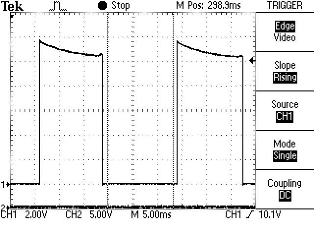
Fig 1: Raw Points Waveform
[Note: the labeling for the vertical axis in the waveform below is incorrect - it's actually 50 volts / division. The probe was a Tek 6009 100X, but the 'scope was expecting 10X.]

As you can see, the points voltage spikes to 230 volts positive to 80 volts negative, with quite a bit of oscillation. This is a normal points waveform.
Installing a 1N4005 diode in series with the signal line to block the 80 volt negative spike, per the VDO tech note, didn't fix it.
The Fix
So, what's with the tach? Seeing as it works fine when run from the pulse generator, my only conclusion is that their input circuit design is marginal to poor, and can't handle the real world. On the other hand, since the tach looks good in the dash, and works well on the bench, maybe we can fix this. So I set about to create my own "front end" buffer circuit.
Fig 2: Prototype board
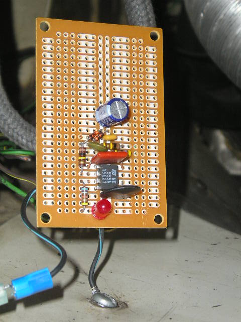
Fig 3: Prototype close-up
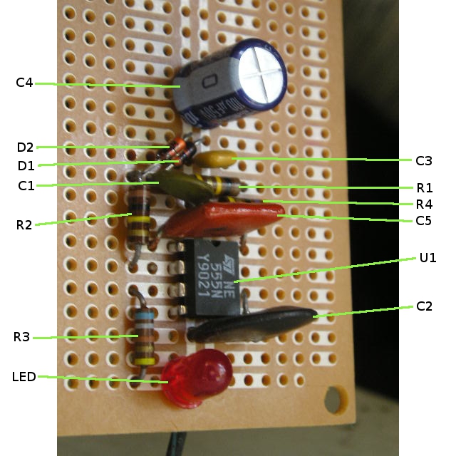
Fig 4: Schematic

Note: this schematic shows R1 broken up into three resistors in series. This is to provide better voltage breakdown protection, as resistors are normally rated at 200 volts. This recommended modification is not shown in the photos above.
Schematic PDFAs you can see, this is a simple circuit, based on the ubiquitous, good for almost anything LM555 timer chip. In this case, we're using it strictly as a Schmitt-trigger inverting buffer. The real work is done in the preceding input signal conditioning circuitry. The prototype was built on a chunk of perf board and cobbed up to the engine so measurements could be made.
How It Works
[The following circuit description is for those of you interested in exactly how the circuit works, so that you can modify or adapt it to your needs.]
The raw points signal enters through resistor R1. R1 has a high enough value such that there is virtually no loading on the points signal. R1 and capacitor C1 form a low-pass filter which removes most of the ringing from the waveform. Diodes D1 and D2 clamp the signal to between 0 and 12 volts.
Fig 5: After one level of filtering
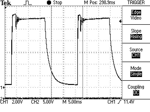
As you can see, most of the nastiness has been removed from the waveform, but not all. We can do better.
R2 and C2 form a second low-pass filter, removing all remaining ringing from the waveform.
Fig 6: After two levels of filtering
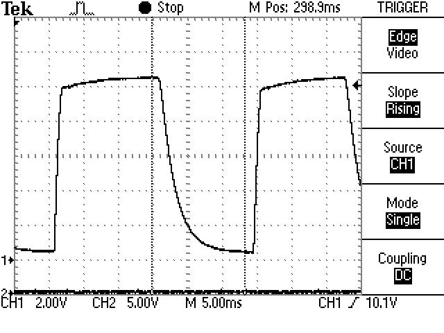
So now we have a nice clean waveform, but the signal impedance is way too high to connect to the tach, so the LM555 chip buffers the signal. This chip can supply about 200 ma of drive, so you should be able to easily drive the tach. Also, this chip can take up to 16 volts of supply voltage, so it should easily survive in an automotive electrical environment. Just in case, resistor R4 was added to act as a fuse, and to smooth out the input power a little. C3, C4, and C5 remove any input power noise. The chip inverts the signal polarity, but the tachometer doesn't care. (See SE555 note below for a better part.)
Fig 7: Final output to the tach
Just for fun, R3 and the LED form a built-in static timing light, in case you have to statically time the engine in the field.
Parts for this circuit used to be available at Radio Shack, but they don't seem to want to be in (this) business anymore. It should be easy to find the parts at Fry's, or on-line (in the USA, Mouser Electronics or Digikey, if nowhere else.)
This pic shows the prototype board cobbed into the engine bay for development.
Fig 8: Prototype in engine bay
Fig 9: Closeup of prototype in engine bay
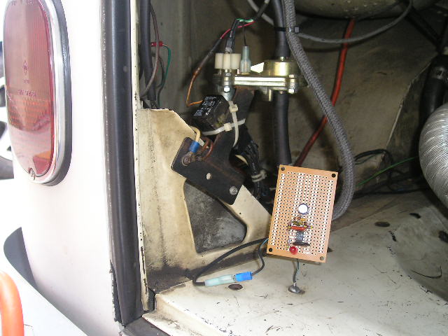
This pic shows why the board was cobbed in where it was - too hard to get probes to the coil...
Fig 10: Hidden ignition coil
Fig 11: Circuit under development

Miscellaneous Details
Since adding this buffer circuit, the tach display is completely stable and smooth, without a hint of jumpiness.
Note: this circuit is designed to operate up to 5,000 rev/min. Thus, it should be adequate for stock engine speeds. For higher speed operation, the low pass filter capacitor (C1, C2) values will need to be reduced. While the roll-off (3db) point is inversely proportional to the capacitor value, You will have to determine the values experimentally.
Side note: the lamps in the tach were way too bright at night, compared to the other dash instruments. This was solved by adding around 18 ohms in series with the feed wire to the lights. You can use an 18 ohm 2 watt resistor. I used four 4.3 ohm, 1/2 watt resistors in series (because I had them in stock), covered with a length of heat shrink tubing.
Final Thoughts
So, you may ask, this seems a little complex for what it does. For me, it solves several problems: (a) makes the tach work flawlessly, (b) avoids running a multi-hundred volt points signal all over the bus, incurring electrical noise in the audio equipment, and (c) isolates the signal line from the points so that any failure or loading in wiring downstream won't affect engine operation. In the future, I plan on adding a circuit to drop power to the AC compressor above a preset speed, so that you can go fast when needed without worrying about the compressor over-speeding and blowing up.
Updated Info
While probing this tach buffer circuit with it connected to an ignition coil being driven by a transistorized driver circuit, I noticed that the primary coil winding was exhibiting very high voltage spikes, well above the normal 350 volts or so that a points-driven coil exhibits. As these voltages well exceed the rated voltage of a normal 1/4 watt carbon film resistor, I feel it would be wise to substitute several lower value resistors in place of R1 (100 kohms). I suggest three 33 kohm resistors in series, as shown in the schematic. This will reduce the peak voltage across any single resistor to a more reasonable value, regardless of the method used to drive the coil. As resistors are a few cents each,the cost is insignificant compared to the increase in reliability.
The SE555 part from TI is a mil spec part, rated at 18 vdc, and will give 2 more volts of voltage tolerance and a much greater temperature range than the regular commercial NE555 or LM555 part, for roughly the same price. If you're ordering parts, this would likely be a good upgrade.
Note: I did not open the tach to reverse engineer it's innards and find out why it works so poorly
out of the box, as it's a new tach and it would have involved mangling / removing the outer trim
ring. If anybody has an old tach that they would be willing to donate to the cause (non-working is
fine), I'll open it, document it's innards, and post the results here. I'm sure it's modifiable
internally, so it will work right without an external circuit. If the tach isn't working,
I'll try to fix it, free, assuming parts are available, and return it to you. Email me if interested.
Per my standing request (above), someone finally sent me a dead VDO tach for analysis (thank you, Marc!) The reverse engineered internal circuitry (specifically, the input network) is shown below (the rest of the circuitry is pretty much out of the On Semiconductor CS8190 datasheet):
Fig 12: Tach Input Circuit
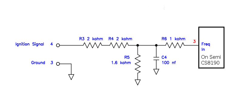
As you can see, there is no signal clamping and minimal filtering. I suspect that this is to make it somehow compatable with both an ignition signal and an alternator connection, but it is a bit of a compromise. Now the chip datasheet states (in a fine print note) that the voltage at the input to R6 (a required component, per the datasheet) must be limited to a range of -1 volt to Vcc (+12 volts), and that the pin #3 input has an internal 12 volt zener diode to ground. Considering the signal from the coil is generally in the +300 / -150 volt range (see waveform below), this specified limit is likely being violated.
Fig 13: Waveform at Tach Input Terminal (Ch 1)

It appears that their circuit suffers from two problems:
- It has insufficient high frequency filtering of the primary waveform.
- It has too much attenuation (used instead of clamping).
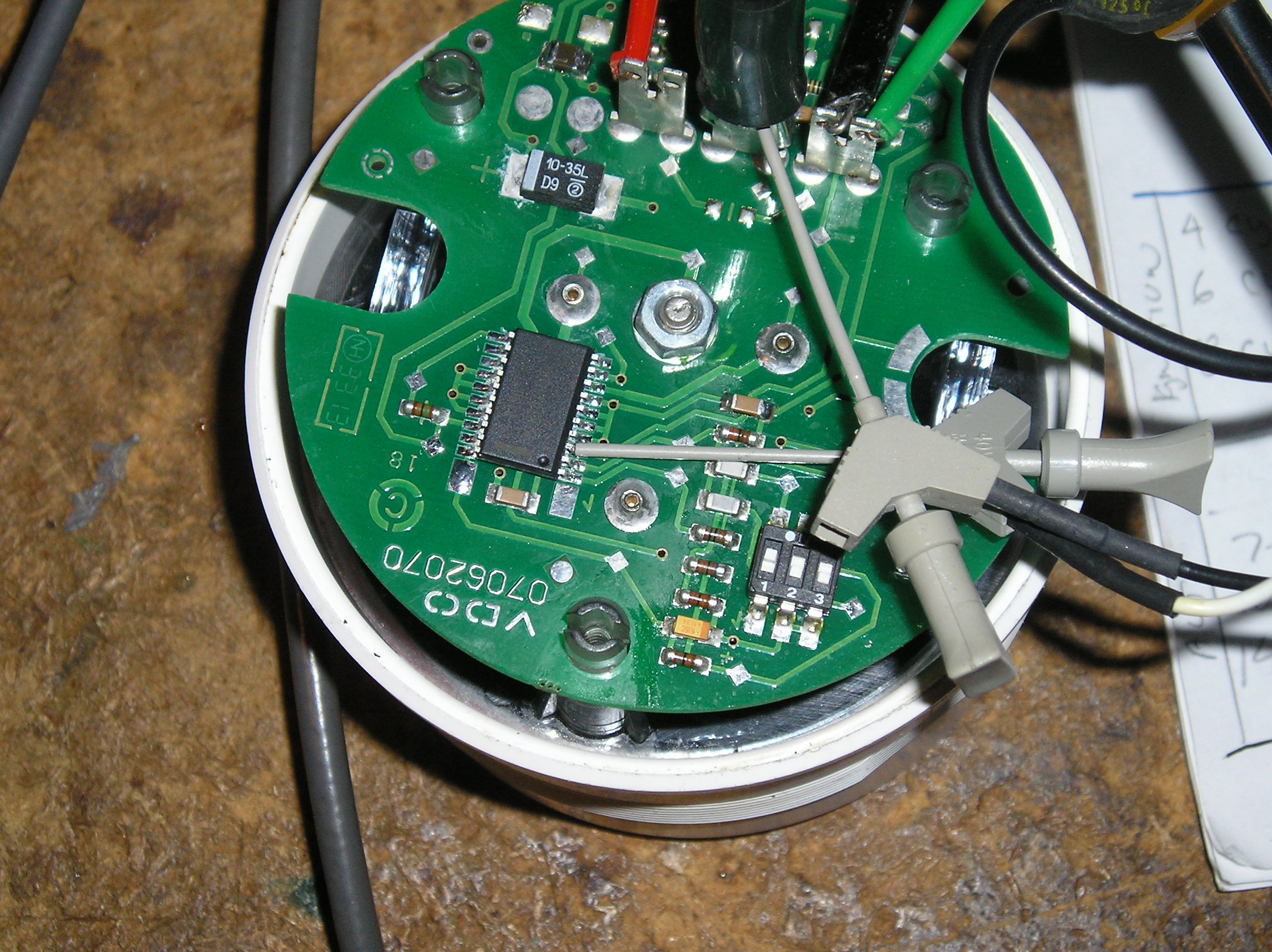
Fig 14: Tach Test Overview

Fig 15: Tach Closeup, Under Test
 Referring to the following 'scope image, taken probing the pin #3
input to the chip, let us examine these assertions.
Referring to the following 'scope image, taken probing the pin #3
input to the chip, let us examine these assertions.
Fig 16: Waveform at CS8190 pin #3 (Ch 2)
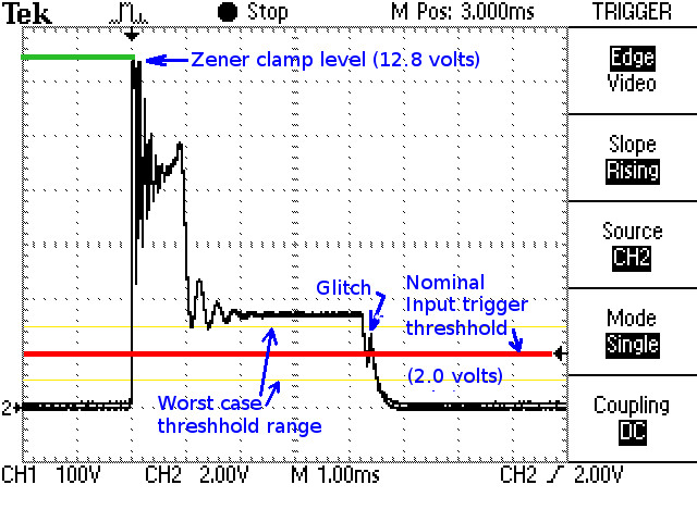
As you can see, there is lots of the ringing waveform of the tach input signal present. Were any of this to cross the input triggering threshhold, it could cause false triggering. This could be removed by clamping the signal and adding another stage of filtering.
The raw input signal has been attenuated by a factor of 3.5 by the input resistor network, and the worst of the high voltage spikes removed by the capacitor. However, there is still enough voltage to trigger the chip's zener clamp. Also, the porch of the waveform, right before where the points close, is at approximately 3.6 volts. While above the chip's 2 volt positive trigger threshhold (nominal: can range anywhere from 1.0 to 3.0 volts), it is low enough that the waveform glitch which occurred as the points closed again transitioned the threshhold level. This is likely enough to cause a false trigger of the chip's circuitry and make the tach reading occasionally jump higher. Decreasing the attenuation and clamping the waveform to safe levels (as done in the input of my circuit) would increase the threshhold margin and likely eliminate this effect.
Because both the CS8190 and the LM555 have high impedance inputs, installing a modified version of my input circuit (R1, R2, C1, C2, D1, D2) in place of theirs, and adjusting the attenuation (probably divide by 2) to match the CS8190 input requirements instead of those of the LM555, should result is a rock-steady tach reading. I'll work up the circuit. Implementing this would, however, require the user to open his tach case and modify the circuit, likely voiding any warranty. Thus, for the average user, constructing an external circuit may be more practical.
Circuit Modification
For those interested in doing an internal tachometer modification, I have worked up a filter network equivalent to my original design to replace the marginal VDO input circuit. Testing shows it to be solid through the entire tach range. The component values have been selected to reduce the circuit loading on the ignition system while still operating the CS8190 chip well within the chip's specifications and without requiring activation of the chip's protective zener diode.
Fig 17: New Input Circuit schematic

As you can see, the input stage slightly attenuates and filters the
points waveform, then clamps it to a range of 0 to ~12 volts (battery
voltage).
This chops off most of the nasty ringing from the raw ignition coil
signal.
The second stage of filtering removes virtually all of the remaining
ringing, and attenuates the waveform to a range of 0 to 6 volts.
As the CS8190 trigger level is around 2
volts, there is sufficient overdrive such that any remaining
top-of-the-waveform anomalies are well above this threshhold,
resulting in the tach only seeing the points closing, yielding a
nice and steady tach reading.
The original input network parts were removed from the tach and a
new circuit was constructed.
While surface mount components would have been preferred, because
I didn't have the needed parts in surface mount packaging, regular
leaded components were used.
"Dead bug" style constuction was used.
Old circuit board pads were used as appropriate for component
support.
Only one original circuit trace was cut, to allow insertion of the
final chip isolation resistor.
After construction, the modified circuit was carefully scrubbed
with isopropyl alcohol and a typewriter brush to remove any flux
residue.
This modified circuit still fits nicely into the tach housing.
Fig 18: Overview
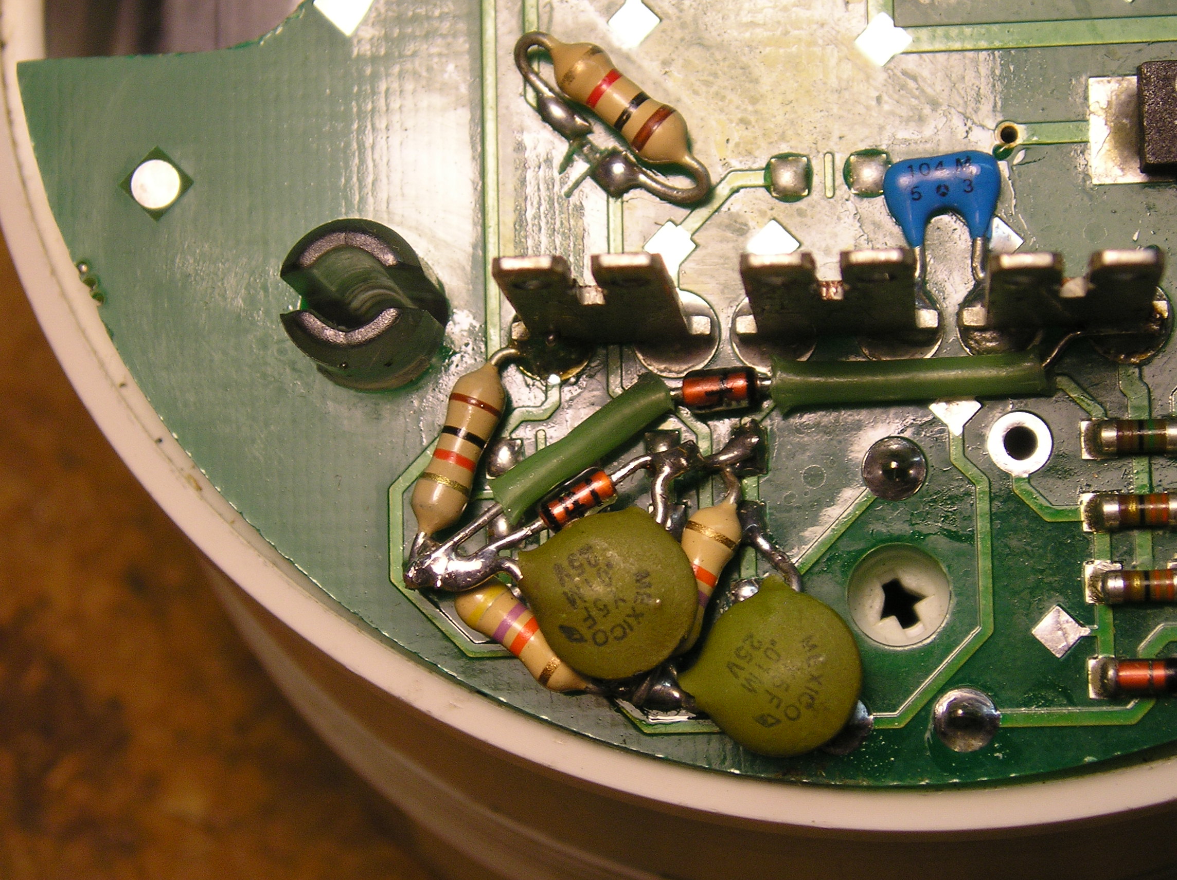
Fig 19: Closeup

[Per my promise, the repaired and modified tach will be returned to Marc as a thank you for the loan of the tachometer, which made this article possible. Thanks again, Marc!]