Introduction
This page represents a collection of useful automotive circuits which can improve the quality of your driving experience in your vehicle. Most are based on the LM555 timer chip, a truly wonderful part with countless uses. Each can be built on a universal grid hobby circuit board (see Radio Shack and others) and enclosed inside a plastic box, or other suitable enclosure. Where fuses are shown, use them; do not omit them.
- Click on any drawing to view a bigger version.
- Click on the links to get printable PDF versions of the schematics.
Fuel Pump Cutoff Relay
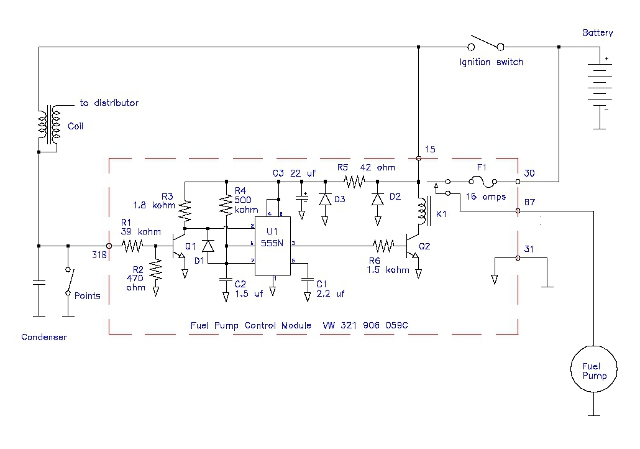
This circuit shows how to wire up a safety control relay (VW p/n: 321 906 059C, internal wiring shown for reference), to automatically start and stop an electric fuel pump as a function of whether the engine is running or not.
It is triggered by the opening and closing of ignition points. It should also work with pointless ignition systems by connecting its input to the switched side of the ignition coil primary. The nice thing about this circuit is that the fuel pump only runs when the engine needs it to. If you should be involved in an accident, or accidentally develop a fuel leak, stopping the engine should stop the fuel pump.
This relay should be installed any time an electric fuel pump is used to replace a mechanical one. These relay modules should be available both new and used.

Schematic PDF
Panel Lamp Driver
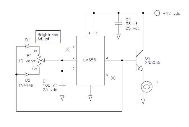
When adding additional engine gauges, it is not unusual to have them be substantially brighter at night than the stock gauges. This circuit will allow their brightness to be adjusted to match the existing gauges, but still have the stock panel dimmer control operate correctly.
Make adjustment R1 a screwdriver adjusted pot. Set it so that the new gauge brightness matches the stock gauges.
Mount transistor Q2 on a suitable heatsink, using an insulating mounting washer and silicone grease, such that it doesn't get too hot to touch.

Schematic PDF
Camper Interior Light Dimmer
This circuit allows interior incandescent lighting inside a motor home or camper to be dimmed. Mount transistor Q1 on a suitable heatsink. As this circuit is a switcher, Q1 shouldn't get very hot.

Schematic PDF
Intermittent Wiper Control
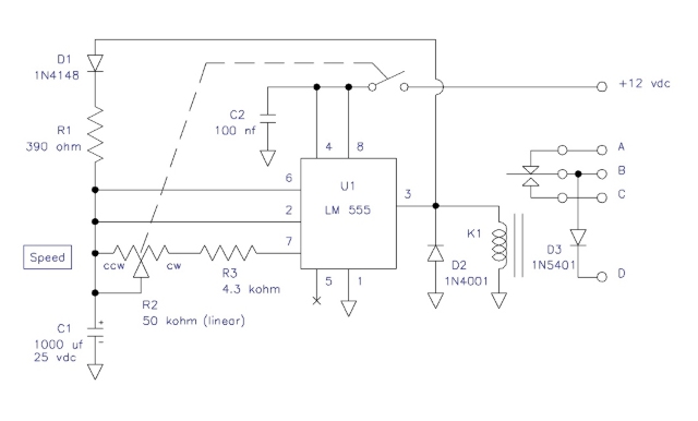
Older vehicles typically did not come with intermittent windshield wipers like modern cars have. It is possible to retrofit such a system by using the following circuit (or a modification of it.) I built this originally for my 1971 VW Panel Van, because having to periodically turn the wipers on and off in misty conditions was annoying.
The base circuit works for all Bay Window Buses (1968-1979). There are two connection methods depending on the model year: 1968-1972 and 1973-1979, as their wiper motors were different.
You may adapt this circuit to other vehicles by understanding that it operates by periodically overriding the auto-park feature of the wiper motor. Relay K1 is activated for a very short time (controlled by R1) which moves the wiper motor off of its park position. The relay then turns off (duration controlled by R2 and R3.) The wipers complete a single cycle, then park. The cycle repeats.
This circuit is intended to be used with the stock wiper switch turned off.

Schematic PDF
Connections for 1968-1972 VW Bus

Schematic PDF
Connections for 1973-1979 VW Bus

Schematic PDF
Four Light to Three Light Trailer Converter
Trailers typically have three active light circuits: left turn / stop, right turn / stop, and taillight. Many vehicles have four light circuits: left turn, right turn, stop, and taillight. You need a converter module to integrate the vehicle's turn and stop circuits into the combo turn / stop lamps for the trailer. You can buy a converter module at the auto parts store. Or you can build one.
The following circuit uses three single pole double throw relays with 12 volt coils, and a pair of fuses to protect against trailer wiring shorts. You will also need a 12 volt battery feeder to supply power to the converter.

Schematic PDF