Introduction
It seems that the replacement voltage regulators being sold for late bay VW busses leave a lot to be desired (like actually working). The way around this is to build your own. To make it even easier, you can build into the case of the old non-working regulator. This way, all of the connecting terminals and mounting is still stock.
The problem
The original regulator design was a zener diode bypass type regulator. Unfortunately, a single bypass diode would have had to dissipate too much power, so two diodes wired in parallel were used. This idea works well if the diodes are precisely matched, so that they share power equally. The diodes normally used by the replacement regulator builders typically aren't precisely matched, so one diode runs hotter than the other. It eventually fails, shifting all the load to the second diode, which quickly follows the example of the first diode. Once both diodes give up the ghost, your fuel gauge now runs on full battery voltage, increasing power dissipation in these components by a factor of almost eight. Quess what happens to them?
The Solution
The first thing to do is open the original regulator and gut it. The case cover should unsnap. You will have to unsolder the diode connections to the baseplate to remove completely. Unsolder the big resistor and diodes, and discard. Next, buff and solder the cover terminal rivets to the terminals and internal metal parts. These rivets are usually loose and make poor contact. Soldering them fixes that.
Note: the male terminal is the input power from the fuse block, and the female terminal is the regulated output power to the fuel gauge. The mounting tab is ground.
The following components are needed to build the new regulator
circuit:
Parts list
- LM317T adjustable voltage regulator integrated circuit
- TO-220 insulating mounting kit for the regulator
- silicone thermal mounting grease
- 100 nf 50 volt capacitor
- 1.0 uf 25 volt capacitor (may be polarized)
- 240 ohm 5% 1/4 watt film resistor (metal film preferred, otherwise carbon film)
- 680 ohm 5% 1/4 watt film resistor (metal film preferred, otherwise carbon film)
- 100 ohm trim pot (multi-turn preferred)
- #22 AWG insulated wire
- 6" tiewraps (for case reassembly)
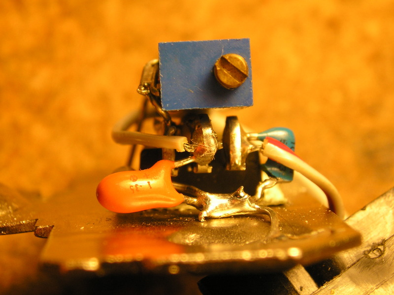
Drill a suitable hole in the baseplate to mount the regulator chip. Position the hole to center the circuit, and allow sufficient clearance at the chip's lead end for wiring. Because the tab of the regulator circuit operates above ground potential, mount the regulator to the baseplate using the insulating mounting kit. Smear a film of silicone mounting grease on both sides of the mica (or rubber) insulator, to maximize the thermal transfer ability. Verify that there is no short between the regulator tab and the baseplate. Roll a loop on the ends of the center and rightmost regulator lead so that wires may be soldered on later.
Next, solder the remaining parts into the circuit.
The component leads provide their support.
(This is known as 'dead bug' [the insect, not the car...]
construction.)
Component Installation
- For directional reference, orient the regulator leads so that they are down and the regulator mounting tab is up.
- 240 ohm resistor from center regulator lead to left side lead. Resistor body at center lead
- 100 nf capacitor from regulator right lead to baseplate.
- 1 uf capacitor from regulator center lead to baseplate. Positive capacitor lead to regulator.
- Rightmost regulator lead to 'cw' end of trim pot and to trim pot wiper.
- 680 ohm resistor from baseplate to 'ccw' end of trimpot.
- 3" length of wire to right side regulator lead.
- 3" length of wire to center regulator lead.


The wire from the right side regulator terminal is the input power. It connects to the male connector on the unit cover. The wire from the center regulator terminal is the output power. It connects to the female connector on the unit cover.

It is recommended that the circuit now be tested and adjusted. Carefully inspect the circuit for miswiring and shorts. Connect a current-limited 12 volt source between the male connector and the baseplate (positive to terminal, negative to baseplate). Connect a voltmeter between the female connector and the baseplate. If a current limited power supply isn't available, use a regular 12 volt voltage source, and place a test lamp (like an automotive tail lamp bulb) in series with the positive power supply lead. This way, if there are any undetected shorts or miswiring, the lamp will light, limiting the current, and the regulator chip won't be instantly killed.

The voltmeter should read somewhere around 5 volts. Adjust the trim pot for a reading of 5.10 volts.

Now carefully press the wires into the case cover, and snap the cover into place. Secure the cover with cable ties.

There you have it - your own precision fuel gauge voltage regulator. The LM317T regulator chip can supply up to 1.5 amps of current, which should be way more than the fuel gauge requires. Note that the unit will dissipate some heat into the baseplate, and thus may be warm to the touch. It should not be HOT! If it is, turn off the power and look for shorts or faulty fuel gauge components.
Schematic
 Download