[Click on any picture to view full size version]
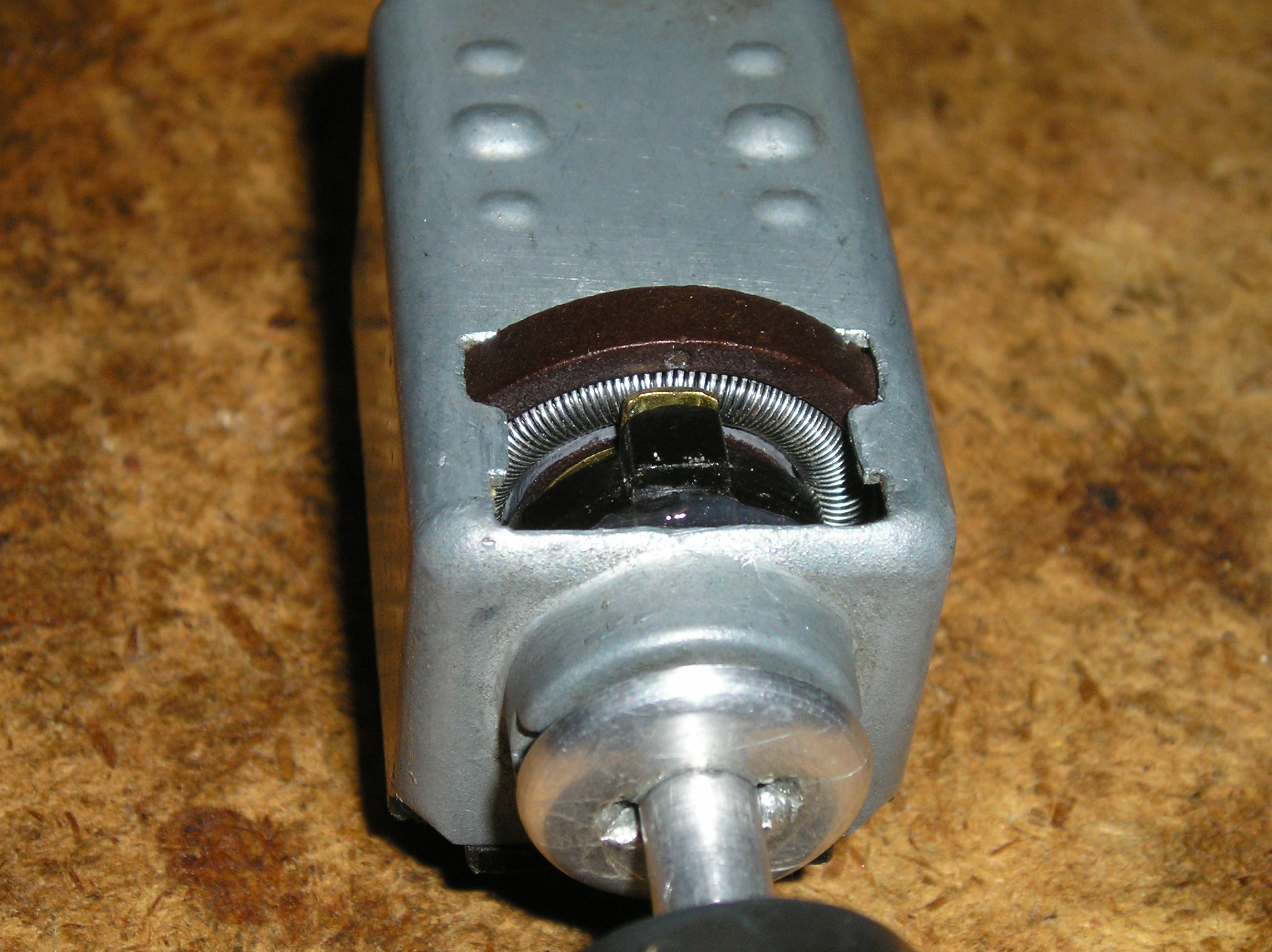
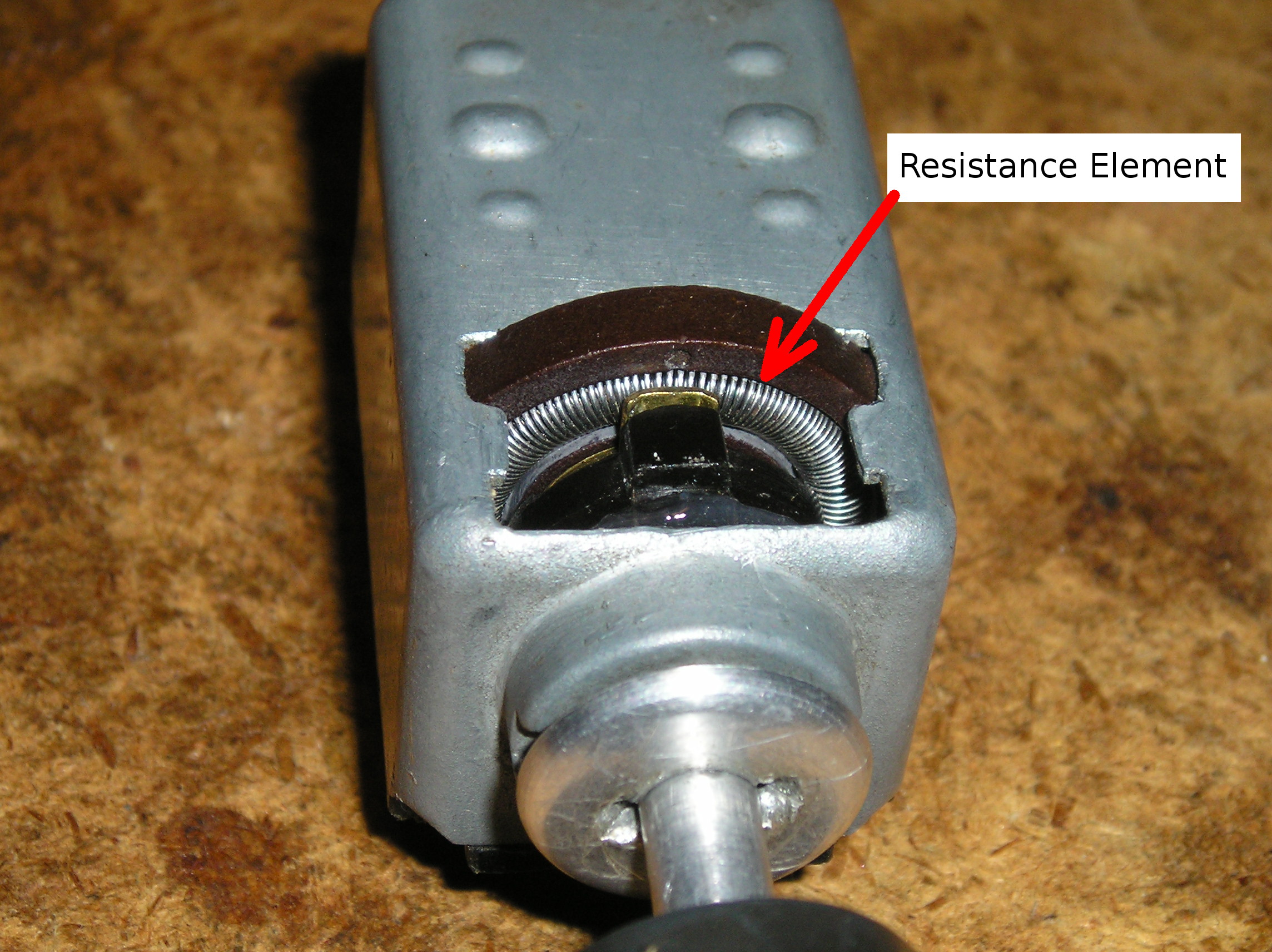
The typical failure mode of an air-cooled '70's vintage VW headlight switch is for the dimmer rheostat to have its resistance element get loose and fall out of its holder.
If you can catch the failure before it wads itself up and/or wraps itself around the switch shaft, then it is possible to repair it. But it's not easy.
So, if it's a lot of work, why wouldn't one just go out and buy a new switch, and be done with it? Well, two reasons:
- The switch is No Longer Available
- The replacement switch is available, but is east-Asian junk.
The first factor applies to 68-71 Bus switches that have a terminal #57 which connects to the green instrument cluster indicator. The second factor applies to everything else.
So you see a reason to overhaul the switch, but wonder what the difficulty is. In short, it's getting the switch apart. The VW people never intended for you to do this. So, the switch is really tough to open up. But it can be done.
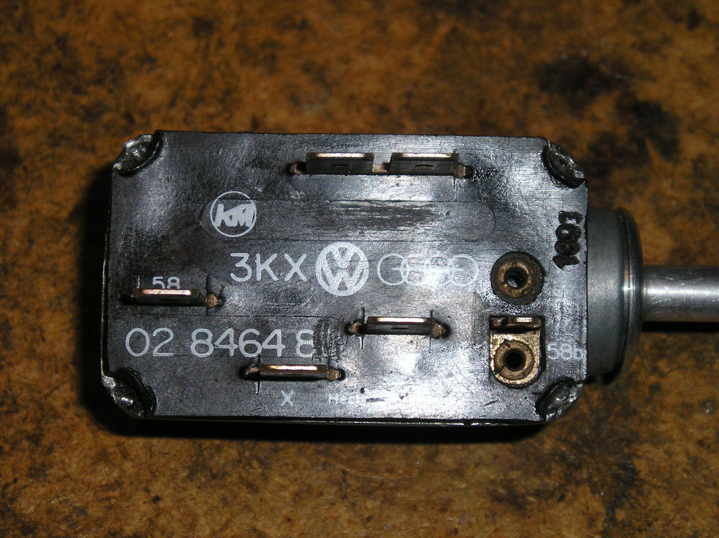
The switch we're working with today is the commonly sold Bus replacement switch 211-941-531e. While suitable for '73 and later buses, it is missing the 57 terminal used by earlier models. It seems strange that this switch would be chosen as the 'universal replacement' when the earlier model 211-941-531 switch will work in all bay window bus models, but I digress...
The first step is to uncrimp the four corners of the metal shell which hold the black plastic switch panel in place. You have to use ice picks and small flat screwdrivers to pry the corner metal back out (but don't stab yourself in the process). It's tedious work. Just keep at it until it's done. Note: this is a diecast housing, and only bends once. Thus, expect small pieces to break off. DON'T break the plastic switch panel!
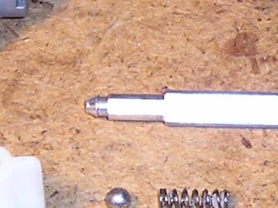
The second problem is getting the switch shaft out. The end of some shafts have a small cone on the end which plugs into a hole in the end of the white plastic slider. It is sort of a one-way process, not intended to come out easily. When I disassembled this switch, I had no idea that this shaft would unplug, so I jockyed the whole mechanism out of the case fully assembled. I later unplugged the shaft using a small modified battery terminal puller.
Note: other versions of switch shafts are peened onto the slider. These switches have a hole in the far end of the case that you can see the peened end of the shaft. If you have one of these, you might be able to drill the end of the peened shaft, releasing the shaft from the slider. To reassemble, you will likely need to machine the shaft in a lathe. Drill and tap the shaft to take a small machine screw. The screw will substitute for the peening on the shaft end. Use some Loctite to retain the screw.
In any event, the switch was finally disassembled. The resistance element was carefully removed from its housing.
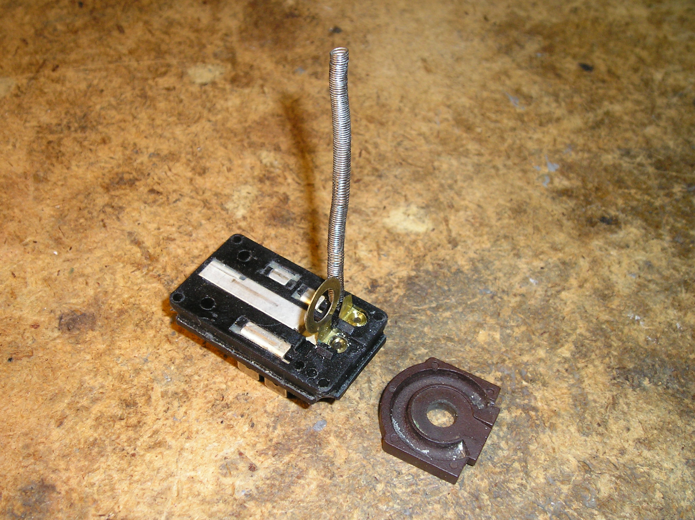
Insert a small Phillips screwdriver or ice pick type tool into the end of the resistance element to act as a mandrel. This needs to be a snug fit, but must not damage or expand the element coils. Once on the mandrel, the element can be carefully scrubbed with alcohol and a flux brush to remove any remaining old cement. Do the same with the brown plastic element housing. Try to contract any stretched areas of the coil such that the entire coil is uniform in coil turn spacing.
To glue the coil back into its housing, I used the old stand-by: J-B Weld. Before gluing, rough up the inside of the housing where the coil sits with some 200 grit wet-or-dry sandpaper. The idea is to create a surface that the epoxy can bond to. Now mix up a small blob of epoxy. Use a small model-painting brush to apply the epoxy. Use a rolling brush movement to coat the housing groove. You don't want a lake of the stuff. On the other hand, you want more than a thin film.
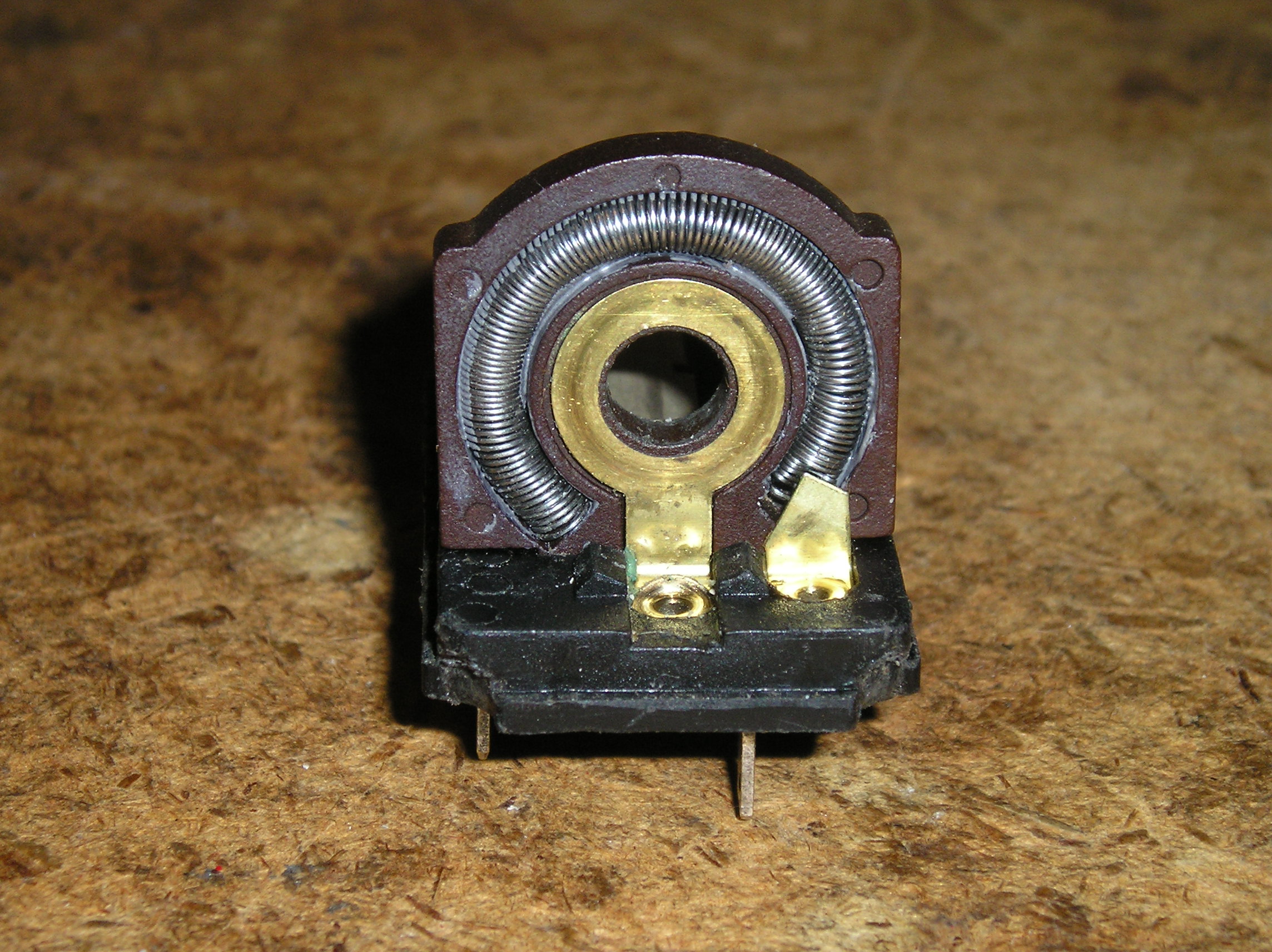
Now position the housing onto the switch base, and press the resistance coil into it. I started the process at both ends, working towards the middle. The coil needs to be uniform in the housing. Use some stiff card paper to make a temporary cover plate. Use a spring clamp to hold the coil firmly into the housing - but not so much as to distort or bend the coil.

Stand the assembly up so that the epoxy tends to puddle in the bottom of the housing. Let it cure in this position.
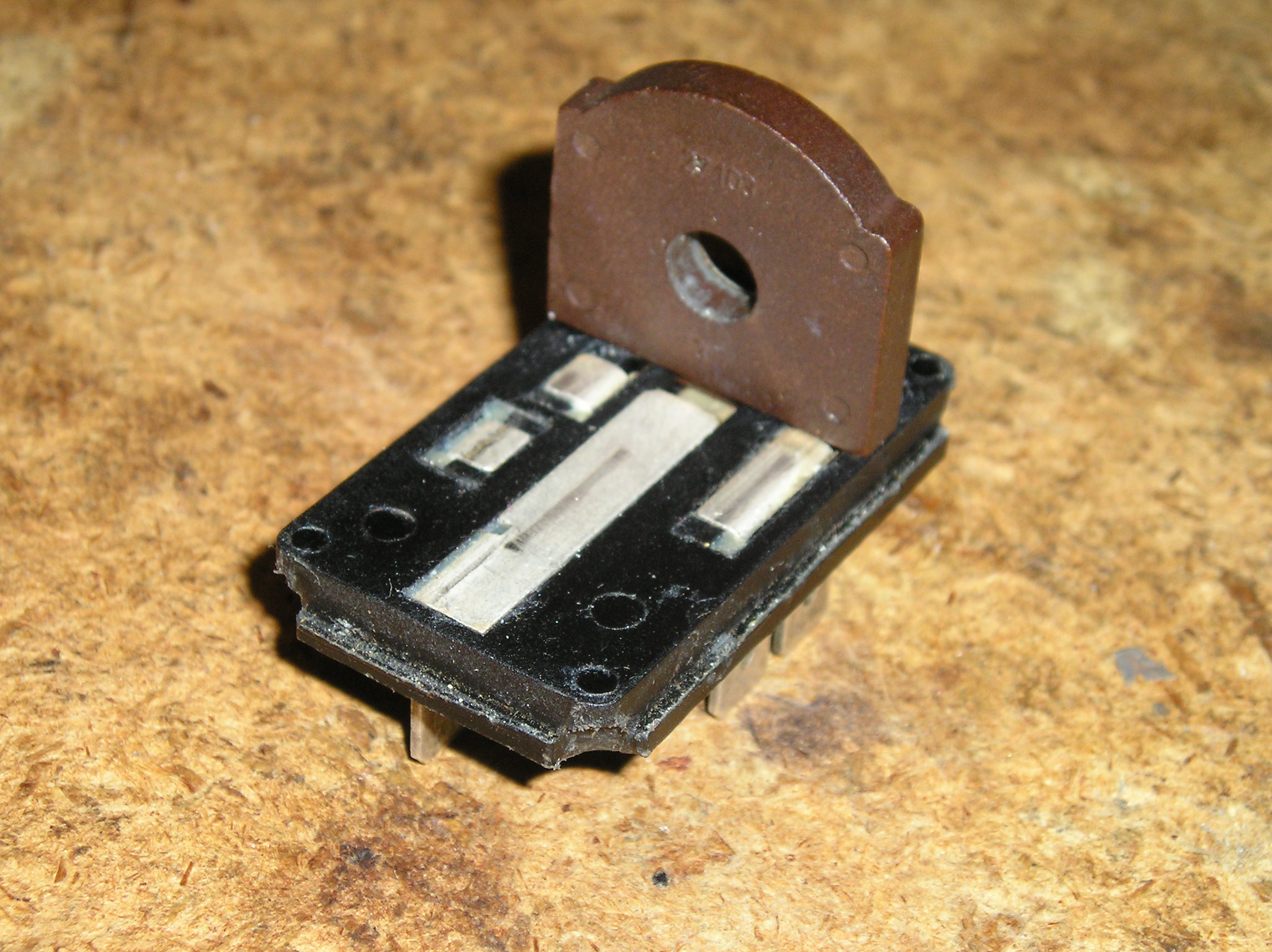
Once cured, remove the clamp and cover paper. The assembly should have nice firm coils, and look like this:
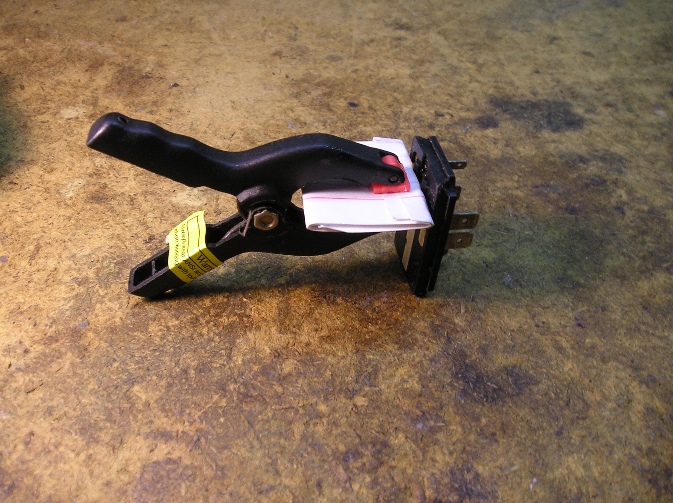
The next trick is to reassemble the switch. Here are the parts, in roughly the correct order:
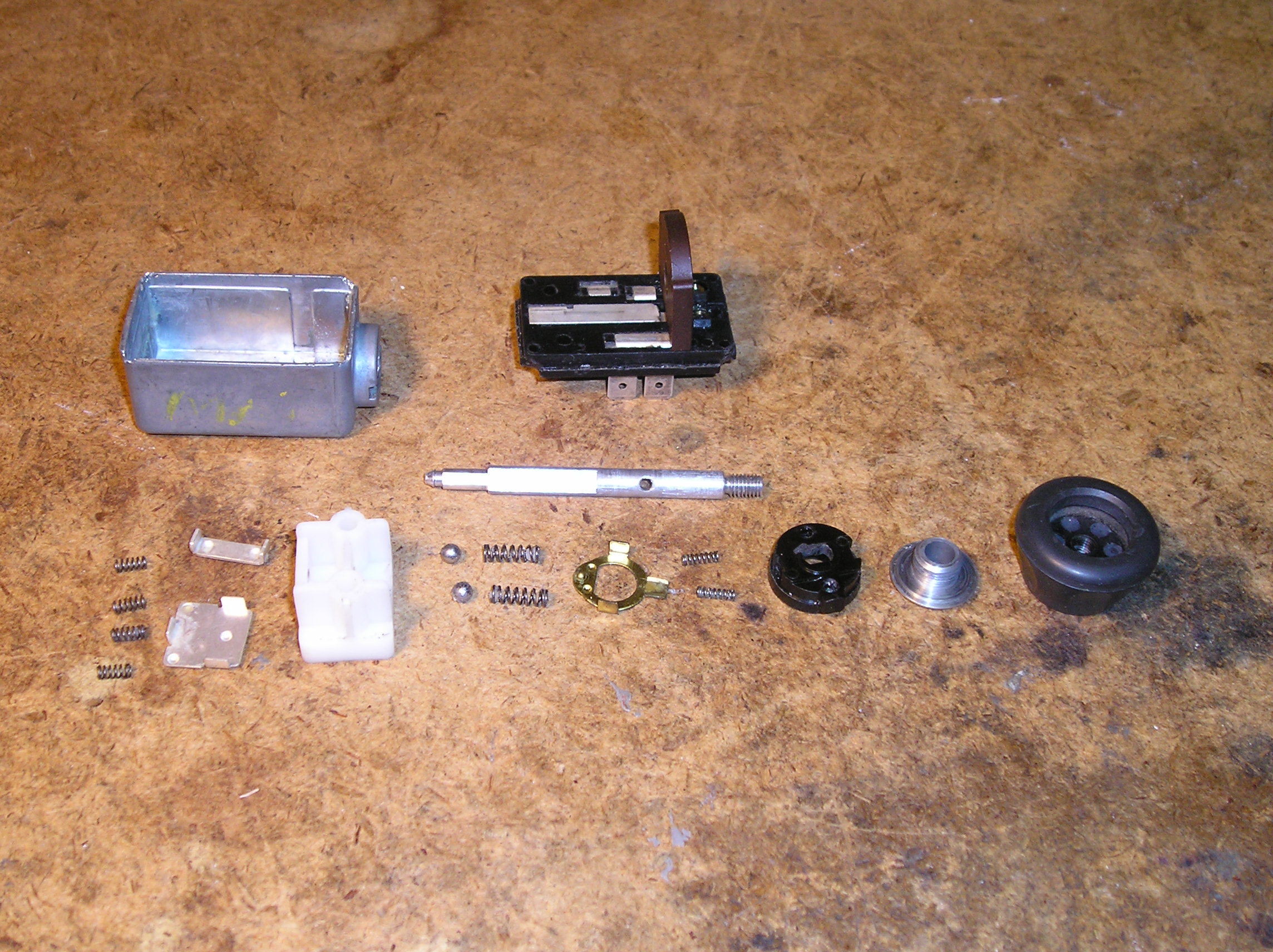
Your best friend here is a tube of dielectric grease. This will help hold all of the small parts, springs, and balls in position.
Here's the assembly order:
- Test-fit the switch base into the metal switch cover to make sure it fits easily. Reshape the metal housing corners as needed so that everything fits. Take a strip of 1" x 1/8" steel bar stock and round an edge on a bench grinder. Clamp it in a vice and use it with a hammer to round the cover corners. Tap - don't pound!
- Insert the four small springs into their holes in the white slider with some grease.
- Place the two metal contact plates into position on the slider over the springs, such that their tabs fit into slots on the white block.
- Paint the switch base with a film of grease. Place the slider into position on the switch base. The correct position has the wide plate on the terminal 30 side of the switch, and the narrow plate on the terminal X side of the switch. Push it up against the dimmer resistor holder.
- Place the two medium springs into their holes in the round black plastic dimmer contact block using some grease. Lightly grease the front face of this block. Place the brass dimmer contact over the springs and into its indexing slots.
- Insert the two large springs into their holes on the white slider. With blobs of grease, stick the two steel balls on the tops of the springs.
- Place the dimmer contact against the dimmer resistor element, with the brass contact touching the resistor coil. Squeeze the block up against the dimmer, and hold the white slider, switch base, and dimmer block like a sandwich. Slide this assembly into the metal cover, and press home.
- Screw the switch retaining nut into the cover to act as a shaft guide. Grease the shaft and insert into the switch, but don't press it home. Rotate the shaft to make sure the dimmer rotates smoothly against the resistance element. Once satisfied that all is working correctly, press the shaft into the switch until it snaps into position.
- Operate the switch to make sure the switch clicks into all three positions (off, park, headlights). Once satisfied, use a pin punch and hammer to peen all four cover corners down, to lock the switch base into the housing. Don't overdo it and crack the switch baseplate! Don't break the resistance element sticking out of the bottom of the switch. Use some wood blocks to keep the element from touching the bench.
The switch assembly is complete. You should be able to rotate the dimmer with no resistance coil movement.