Introduction
Good Original German parts for VW's are getting harder and harder
to find, and their aftermarket replacements are getting to be poorer
and poorer in quality. Thus, it makes sense, if possible, to repair
existing parts and restore them to working condition.
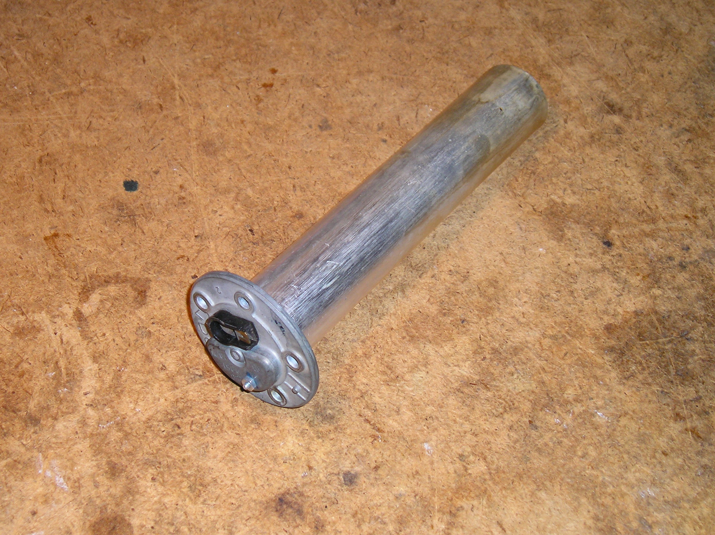
One such part is the fuel sender used on early bay window buses,
1968 to approximately 1972.
The Sender Unit
Tools
You will need some tools to perform this repair. Below is a picture of those I use. You may substitute whatever tools you have which will get the job done properly.

From the rear: 4-40 x 1/4" pan head screws and nuts (in film cans), flux and solder, alcohol, Loctite 242. In the middle: various screwdrivers, flux brush, 4-40 tap, DVM. in the front: tinned 22 ga solid copper wire, twist tie, various pliers and cutters. Not shown: soldering iron, cleaning brush.
Procedure
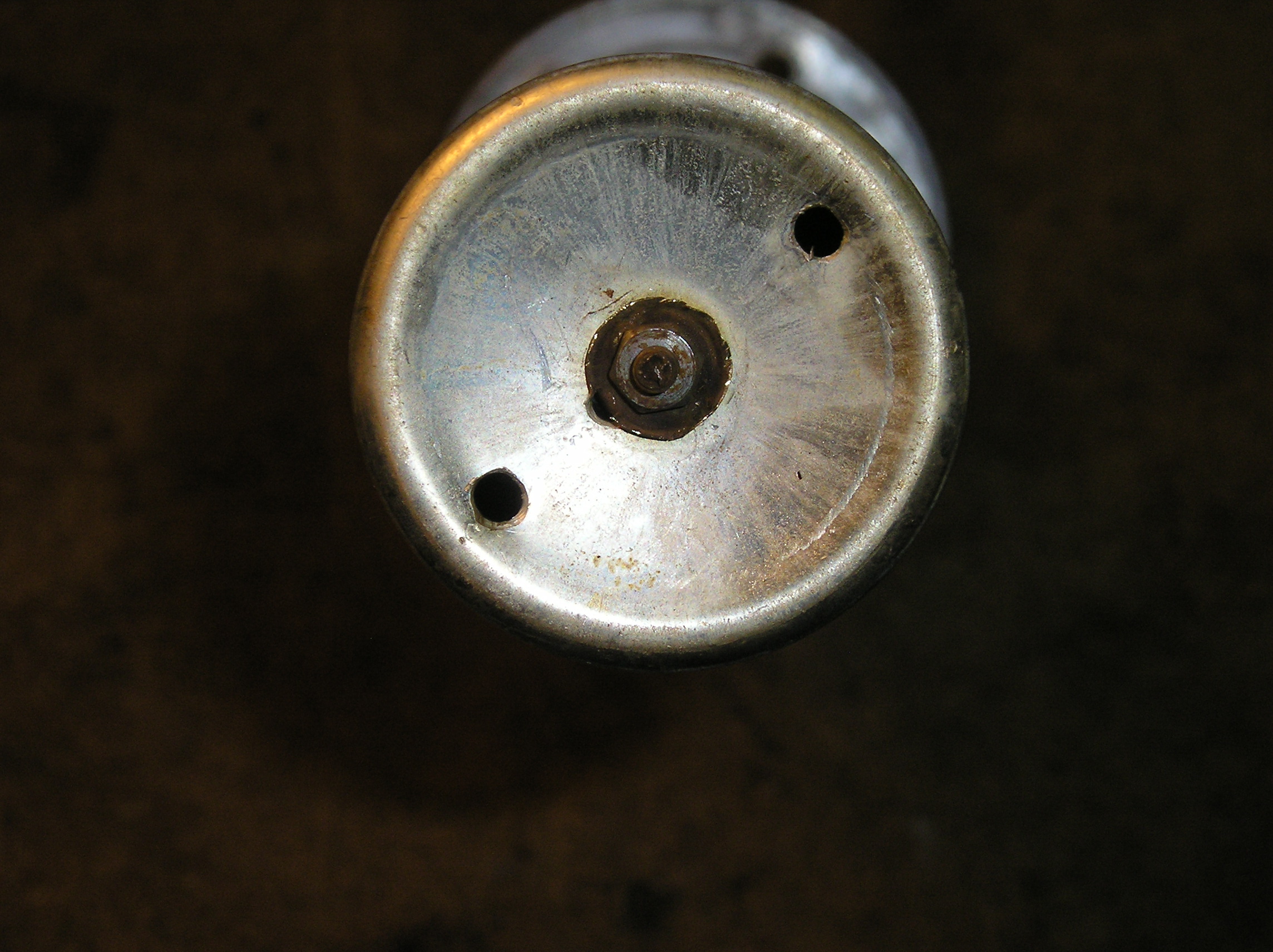
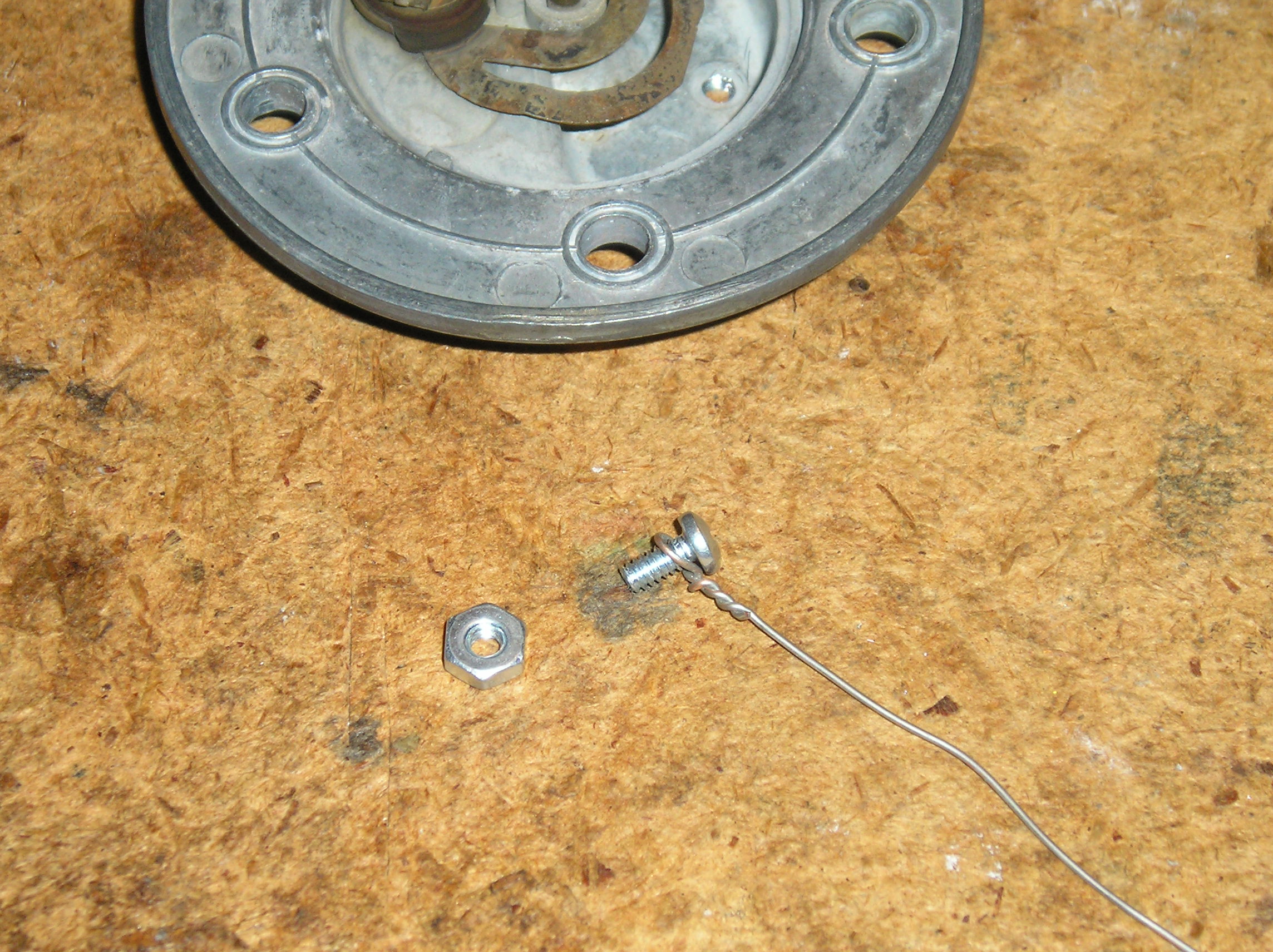
First, you must open the sender so that you can access its internals. To do this, find the nut and keeper located on the bottom of the unit.
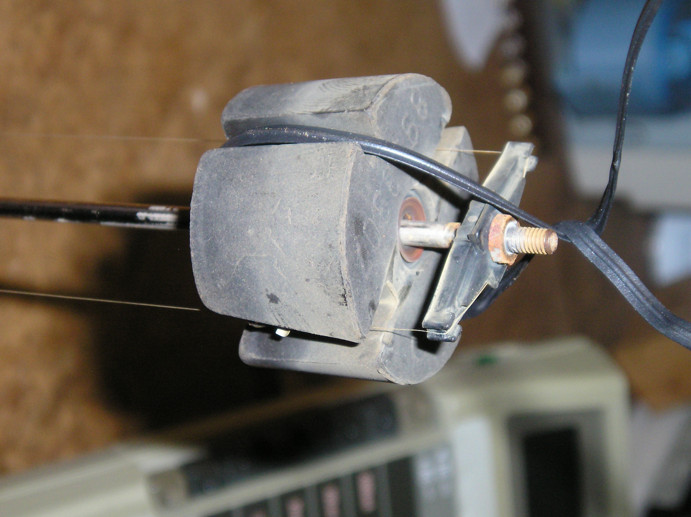
Carefully pry the ears of the retainer away from the nut. The retainer is fairly brittle with age, so pry carefully, as we want to reuse this part. Once the ears are out of the way, apply a little lubricant (WD40, light oil) to the shaft threads, and remove the nut and retainer. Now the covering tube should be removable by pulling it off the sender.
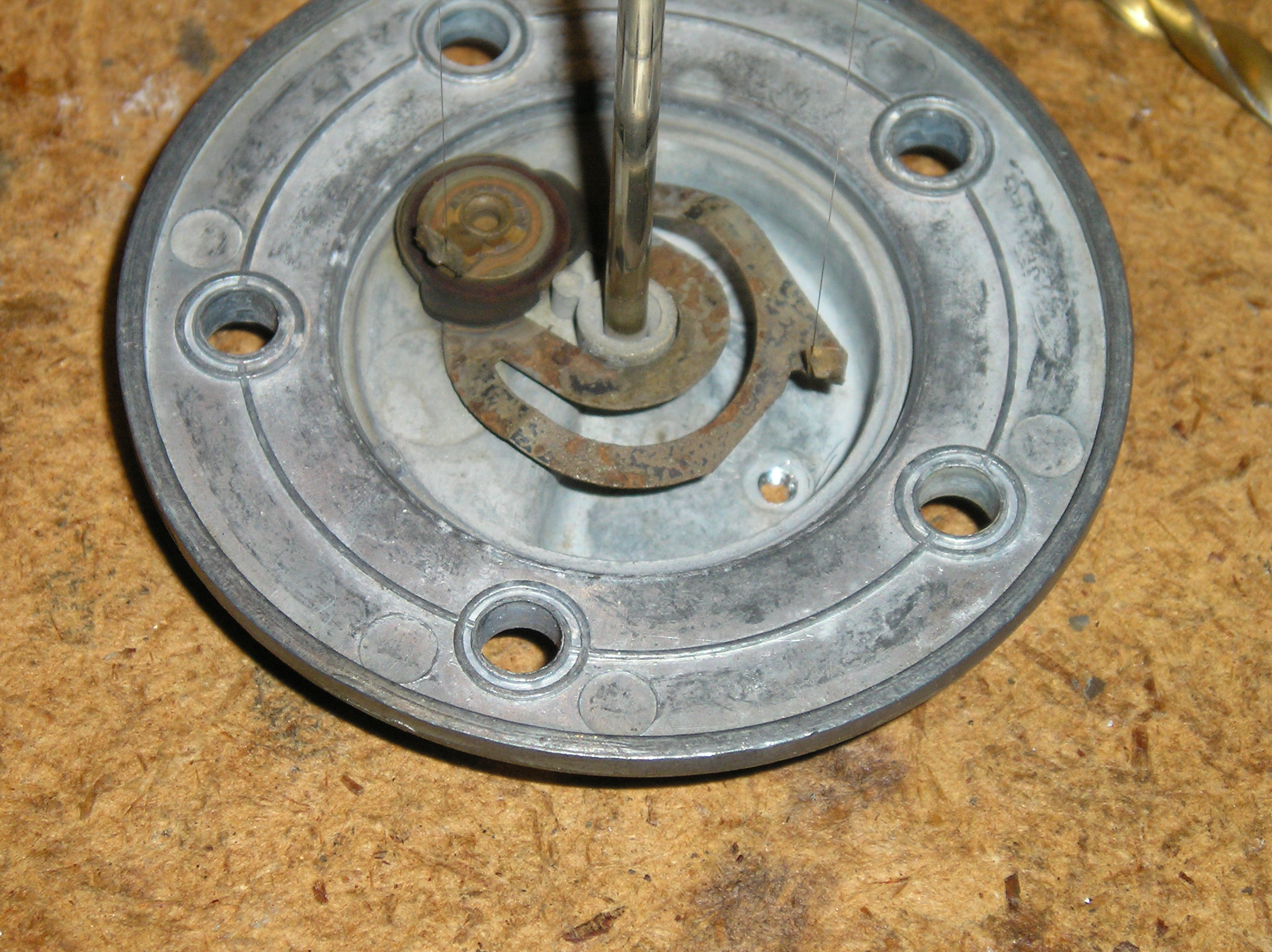
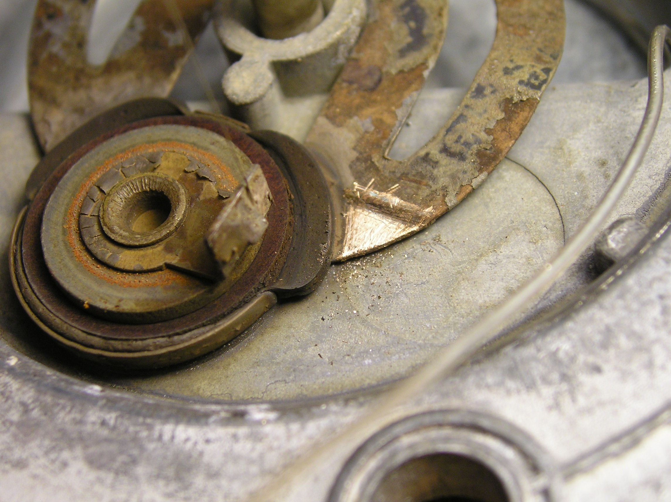
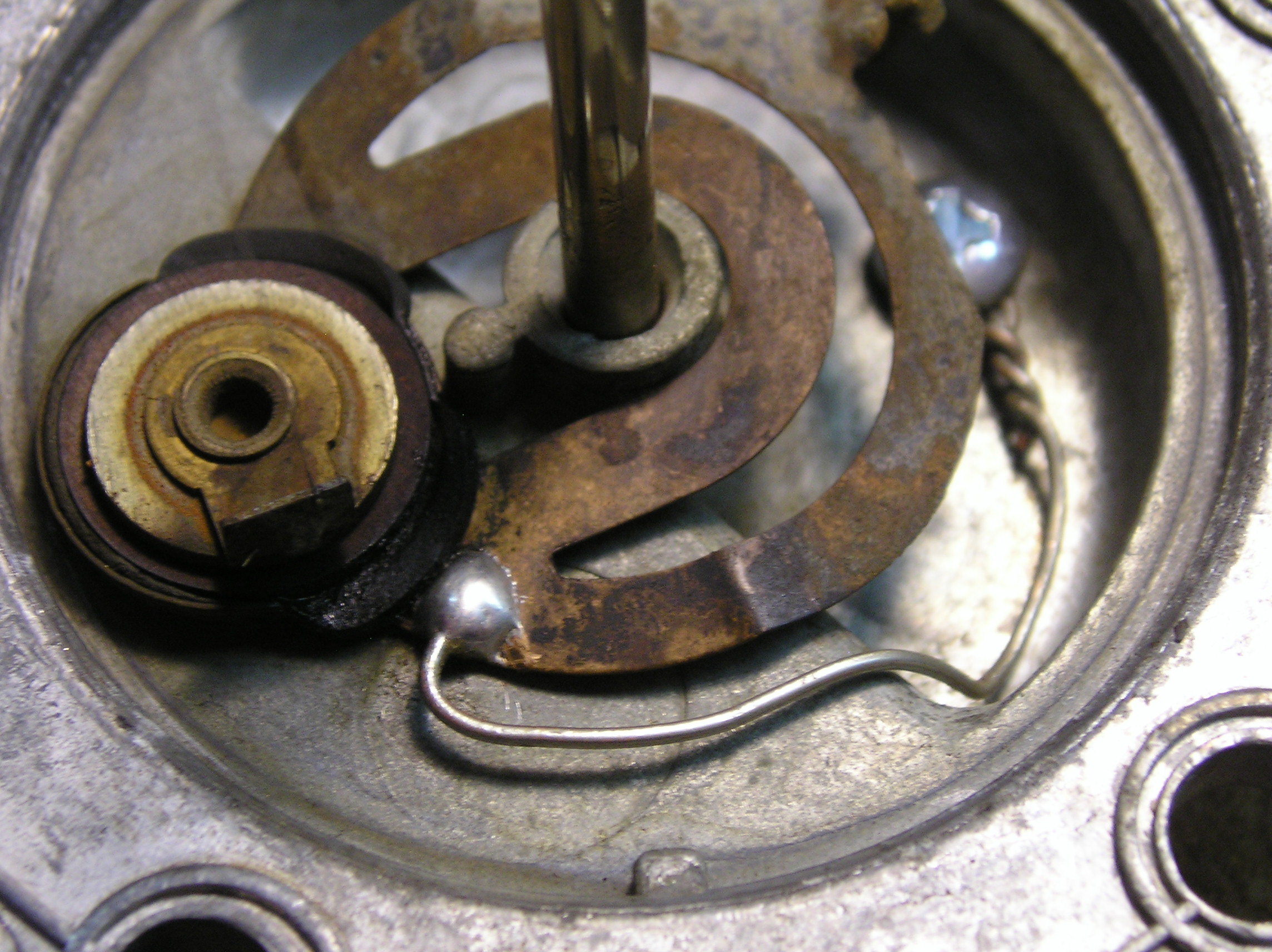
The innards of the sender are fragile, so use caution in dealing with them. You will see a float which slides up and down the center post, and along two fragile resistance wires. Slide the float to the far end of the rod and use the twist tie to keep it there.
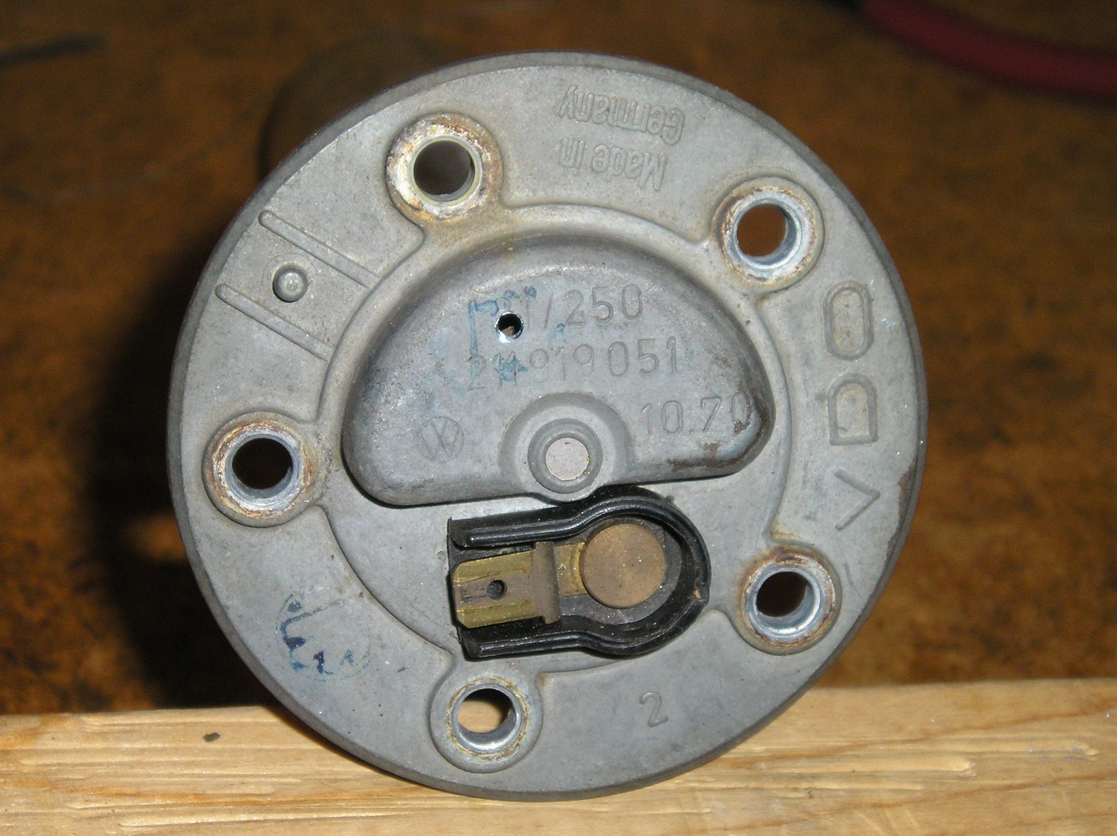
Now lay the unit on its lid with the float pointing up. Inspecting the lid, you will see a spring brass tensioner which keeps the resistance wires taunt. It is pressed against the die cast lid by a rivet and metal and plastic washers. The center rivet is the connection to one resistance wire; the brass tensioner is the connection to the other. The float connects the two wires together.

The most common failure mode in this unit is the connection between the lid (pot metal / zinc / aluminum / ?) and the brass tensioner. As these are different metals, corrosion slowly forms between them. This corrosion adds unwanted resistance to the sensor, messing up its ability to deliver accurate information. As the resistance increases, the fuel reading for a full tank slowly drops, and the fuel gauge will indicate empty way too early. So, what we need to do is eliminate this unwanted resistance.
However, we have a problem: the unit is riveted together and it is impractical to disassemble it any further. So, we will have to find a way to create a better connection here.
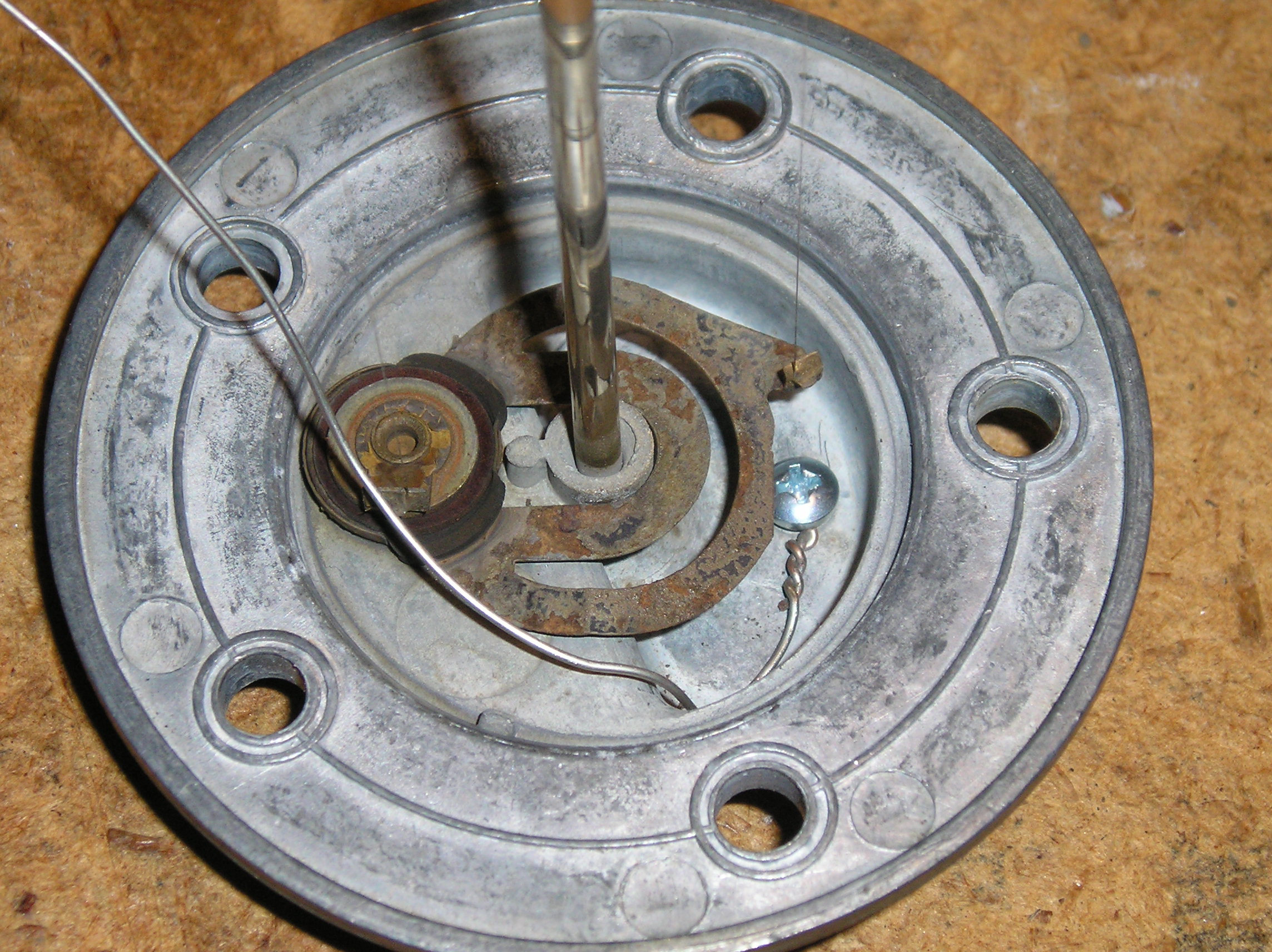
If you inspect the lid casting, you will notice a hollow area below where the resistance wire is fastened to the brass tensioner. What we're going to do is drill and tap a small hole here. We will use this hole to connect a new ground wire to the lid, and then solder that wire to the brass tensioner, thus bypassing the corroded high resistance connection which has formed. The hole should go where shown. As I used a 4-40 screw, i drilled the hole 5/64" in diameter. If you're using metric hardware, drill a hole of the appropriate size for your tap.
Hole Drilled in Lid

Drill carefully so as to not damage the brass tensioner or resistance wires. Afterwards, tap the hole. The metal is reasonably thick here, so you should get a couple of threads. Clean off any burrs and carefully blow off chips with compressed air.
Hole Tapped
Now take a length of 22 gauge tinned copper wire and form a loop at one end. The loop should fit snugly over the end of the screw, as shown. Twist the wire to retain it, but not so much as to weaken the wire.
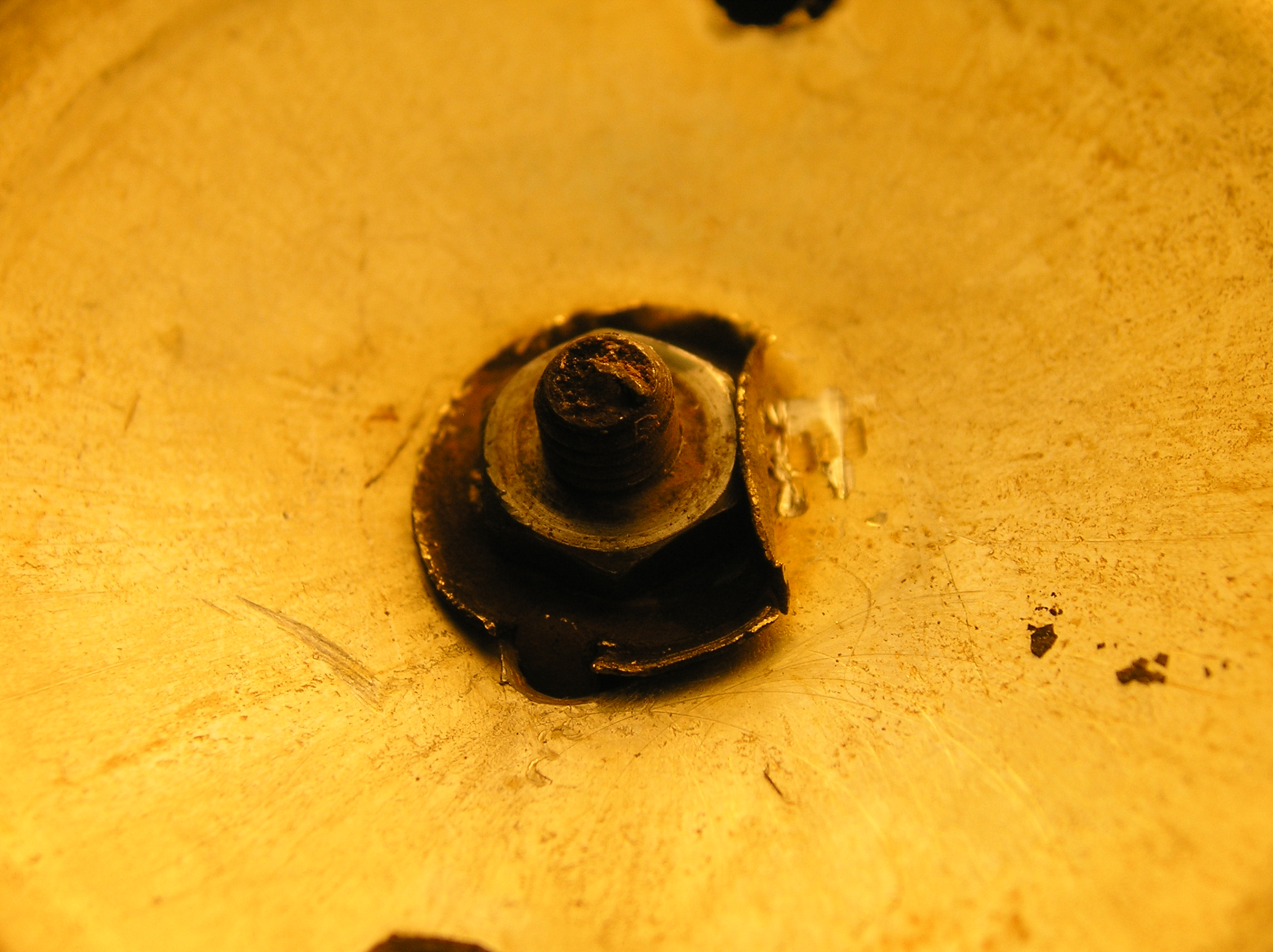
Now insert the wire and screw into the tapped hole from the inside
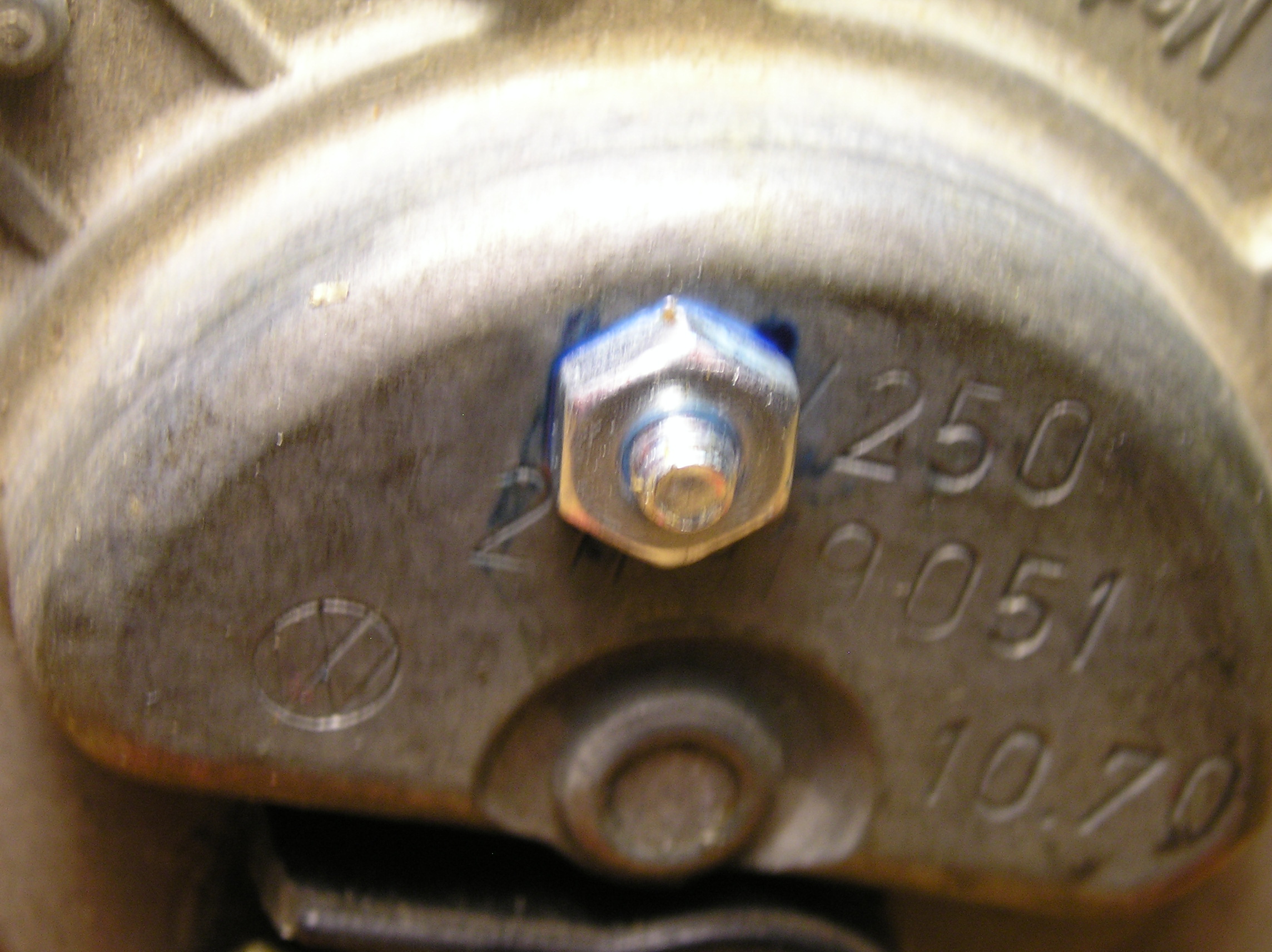
of the lid and tighten. Flip the lid over, put a couple of drops
of Loctite on the protruding screw theads, back off the screw a
couple of turns to get the Loctite into the joint, then tighten
the screw snugly. Add another drop of Loctite, then install and
tighten the jamb nut. Remember, this screw is likely under gasoline
when the tank is full, so make sure the threads are well sealed.
You do not want a fuel leak here.
When complete, it should look like this:
Now you must scrape a spot in the brass tensioner clean and shiny, so you can solder the wire to it. I picked a spot close to the rivet, such that the soldered joint would be as free from any movement as possible.
Take your time doing the scraping. The brass is usually quite corroded, and must be completely clean. Close isn't good enough. Any remaining corrosion will keep the solder from wetting the metal properly, and your soldered joint will fail. When done, it should look even better than this:
Now you must tin the brass tensioner. We're using rosin core solder, 60/40 or 63/37. Unfortunately, the rosin flux in the solder doesn't have the horsepower to get the brass clean enough, so I pre-fluxed the joint with zinc chloride paste flux. Heat the metal with your soldering iron or gun, then add some solder. Heat until the solder flows and wets the brass, but not so much as to melt the plastic insulator next to it.

Now bend and cut the wire so that it reaches the tinned spot on the brass. Tin the end of the wire, and (with your three hands), heat the joint, press the wire into it with a small screwdriver, and add solder as needed. Afterwards, I add a little more flux, and flow the joint a second time, just to be sure.
When cool, fully clean the joint with alcohol (methanol or shellac thinner). You want to remove all traces of flux. [Note: flux is soluble in alcohol fuels, and would love to plug up your carb jets or fuel injectors, so do a good job.] Now blow dry with compressed air. It should look like this:
Now use the ohmmeter to check the resistance from the sender lid to the brass tensioner. It should be close to zero. Also check the resistance from the wire terminal to the other resistance wire. It should also be close to zero.
There are two more areas where a corroded connection can mess up your fuel sender. They seldom fail, but since it's such a hassle getting at the sender, you might as well repair them now.
The first is at the rivet inside the sensor. Scrape clean, flux, and solder as before. Should look like this when done:

The second is between the rivet and the terminal. This joint is harder to clean and solder, and takes more heat. Should look like this when done:

Now connect the ohmmeter between the sender case and terminal. You should get readings near these, with the sender upright and inverted:
![]()

[Added 5/12/17] One final step: take a piece of ScotchBrite pad (or equivalent) and polish the center rod that the float ride on until it is smooth. This rod is subject to corrosion, and will cause the float to hang up as the fuel level drops.
Once the sender has been verified good, reinstall the metal cover tube using the original retainer and nut. Tighten the nut just enough to secure the tube. Now carefully bend the ears on the retainer to capture the nut.
Notes on Soldering
Soldering is a thermo-chemical process where one metal is dissolved in another. In our case, the outer surface of the copper wire is dissolved in solder. Being chemical in nature, the joint must be clean and free of any corrosion or contaminates. This is achieved by mechanical cleaning and chemical cleaning, using flux. The hot flux reacts with trace contaminates and metal oxides, and either converts them to forms compatible with soldering, or floats them away from the joint. Thus, good clean flux, of the proper type, is essential to successful soldering. Do not use acid fluxes, as they lead to long term corrosion issues.
Soldering involves the application of heat. You want a lot of heat, but not a lot of temperature. This is the secret to successful soldering. You want to get the joint hot as quickly as possible (lots of heat), but limit the temperature to a point where the solder isn't damaged. I use a 60 watt Weller W60P soldering iron with a wide 700 degree paramagnetic temperature controlling tip. This iron will dump massive amounts of heat into the joint, but limit the maximum temperature to around 700 degrees F.