Introduction
Various early (1966 to 1969) USA delivered VW buses and bugs have a mysterious turn signal relay unit which confuses most people trying to figure it out. On the typical VW wiring diagram, it looks like this:
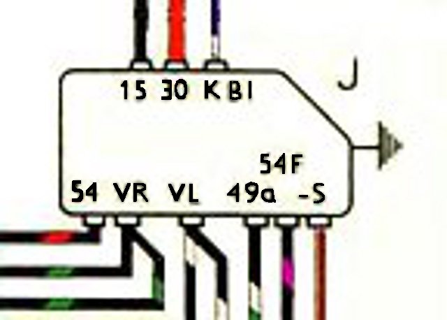
Here's what's functionally inside it:

[Click on the drawing to view a bigger version]
As you can see, the module contains two major subsections: a flasher unit, and a 4-way flasher relay. We will deal with each of these subsections separately.
Each subsection of this module may be tested on the bench. You will need the following:
- A power source to match your flasher (6 or 12 volt), that can supply around 5 amps.
- Two paralleled front turn signal lamps of the proper voltage. Wire the shells of both lamps to a wire and the two center pins to another wire.
- A handful of clip leads to make connections to the 9 pin flasher module.
For all tests, the '-' battery terminal will be connected to the case or center mounting screw of the 9 pin flasher module, and to the shells of the turn signal lamps. Note: make all connections before applying power.
Flasher Unit
The flasher subsection is an electronic version of a standard three or four pin flasher, and works similiarly. You supply it power, and connect a lamp load to its output. The lamp load makes the flasher relay open and close periodically, causing the connected lamps to flash. There is a third connection to the flasher unit which causes the dash indicator to flash. This connection only flashes if the load on the main flasher output is sufficient. This is supposed to tell the driver that all of his turn lamps are good. A bad turn lamp is supposed to stop the dash indicator from flashing.
The flasher unit may be tested by connecting to the flasher module as follows:
- '+' battery to terminal 30 and 15.
- the center pins of two paralleled turn signal bulbs to terminal 49a.
- '-' battery to the flasher module case and to the shells of the turn signal bulbs.
If the flasher unit is good, the two lamps will flash. If you wire a small indicator bulb between terminal 30 and terminal KBL, it should also flash.
4-Way Flash Relay
The 4-way flasher relay reconfigures the normal turn signal wiring so that all four turn signal lamps flash at once, regardless of whether the ignition key is on or off. The position of the turn signal switch is ignored, as is input from the brake switch.
When the 4-way flasher switch is pulled, it grounds terminal S on the module. This causes battery power from terminal 30 to pass through the relay coil, activating the relay. This causes the following circuit changes:
- The source of power switched by the flasher unit is switched from terminal 15 (switched battery power) to terminal 30 (unswitched battery power). This provides powers to the flasher module output, regardless of the ignition switch position. [Note: The power source for the flasher unit itself is always terminal 30.]
- The brake light power to the turn signal switch on terminal 54F, normally fed trom terminal 54 (brake light switch), is instead connected to the output of the flasher unit. This causes both rear lights to flash, regardless of the position of the turn signal switch or the brake light switch.
- The front turn signal lamps on terminals VL (left) and VR (right) are connected to the output of the flasher unit, causing them to also flash.
The relay coil can be tested by connecting '+' battery to terminal 30 and '-' battery to terminal S. The relay should click.
The basic switching function may be tested by connecting as follows:
- '+' battery power to terminal 30.
- '-' battery power to terminal S, the module case, and to the shells of two turn signal bulbs.
- The center pins of both turn signal lamps to terminals 54F, VR, and VL, in turn. Connecting the lamps to any of the above three terminals should cause them to flash. Ungrounding terminal S should stop the flashing.
The final circuit to check is the brake light switch pass-through: Test as follows:
- Connect '+ battery to terminals 30, 15. and 54.
- connect '-' battery to the shells of the turn signal bulbs and to the case of the 9 pin flasher.
- connect the center pins of the turn signal bulbs to terminal 54F. The lamps should light.
- connect '-' battery to terminal S. The relay should click, and the lamps should flash.
Flasher Unit Repair
The most common point of failure of these units is the contacts on the 4-way relay. The main source of the damage lies in the fact that all power supplied to the relay is unfused. Thus, any excessive load or short on a relay output terminal results in contact damage, or distorted contact arms caused by heat. Generally, dressing with 320 or 400 grit wet-or-dry sandpaper, or a thin points file, will repair the damage. Access to the contacts can be problematic, but perseverance furthers. Keep at it. Carefully bend the contact arms close to the support body if alignment corrections are needed.
Final Thoughts
Once you know what's inside the 9 pin flasher, and you know how it works, much of the mystery of this device disappears. Examine the schematic to understand what's inside. Follow the tests above, and conquer your 9 pin flasher.