Introduction
It's sometimes necessary to have a true three phase signal for testing various electrical devices. Most labs don't have a source of three sine waves phased 120 degrees apart. This circuit allows these equally spaced sine waves to be generated from a single master input signal. See the following circuit:
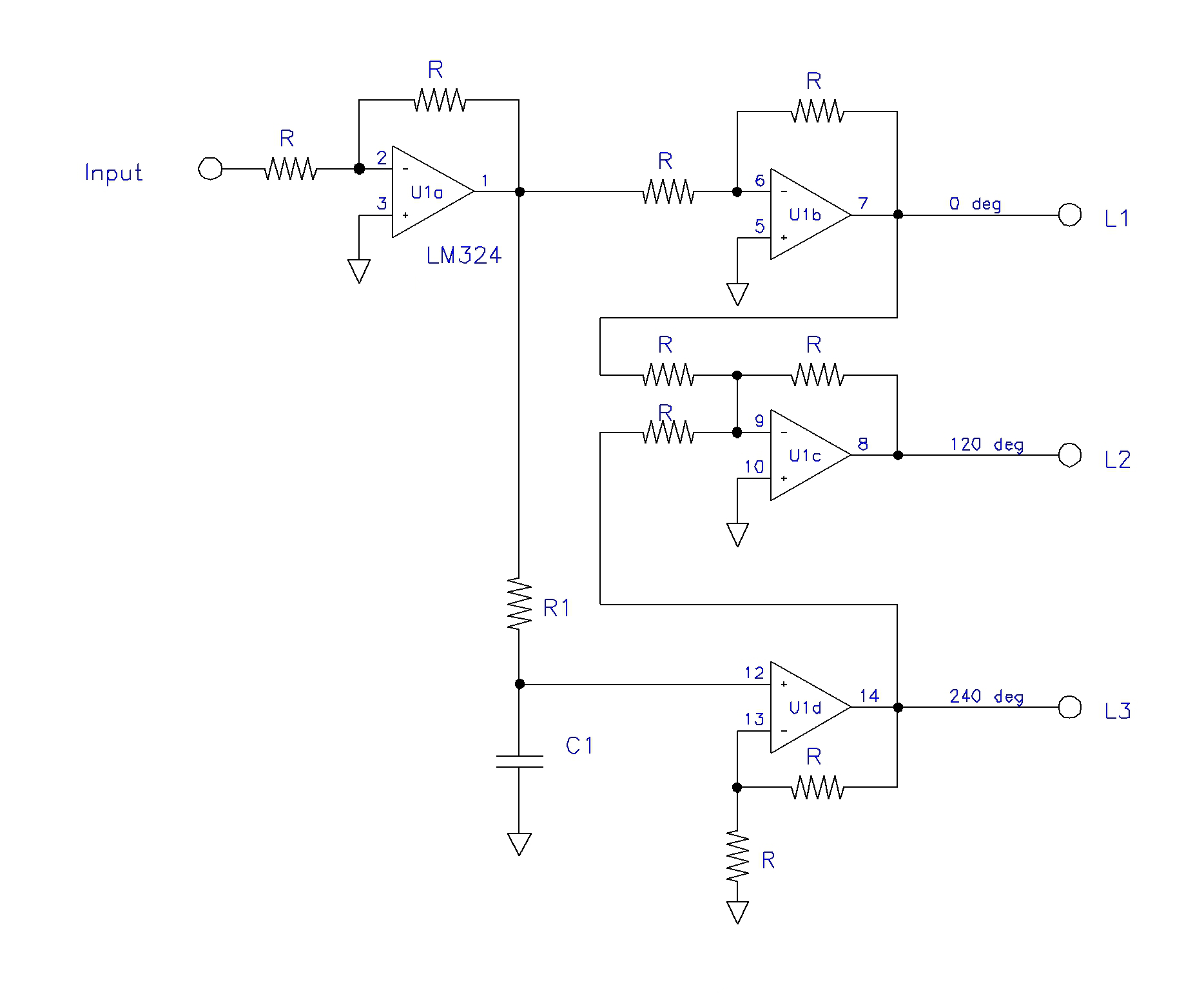
Schematic
Notes:
- all R = 10 kohms
- U1 = LM324 / equiv
- power = +/- 12vdc
| Frequency (hz) | R1 (kohms) | C1 (nf) |
|---|---|---|
| 1000 | 2.7 | 100 |
| 400 | 6.8 | 100 |
| 60 | 4.7 | 1000 |
| 50 | 5.6 | 1000 |
(values approximate)
Description
The circuit works as follows: The input sine wave is inverted and buffered by unity gain op amp U1a. Its output is becomes the master signal.
The master signal is inverted again and buffered by unity gain op amp U1b. Its output becomes 0 degree phase signal L1.
The master signal is phase shifted 60 degrees by RC network R1 C1 and applied to amplifier U1d. This non-inverting amp has a gain of two, compensating for the signal loss in the RC network. Because the master signal is phase shifted 180 degrees from the input signal, and shifted an aditional 60 degrees by the RC network, the final signal is shifted 240 degrees, and becomes the L3 phase signal.
Unity gain amp U1c adds the L1 (0 degrees) and L3 (240 degrees), yielding a 300 degree phase shifted signal. It is then inverted, effectively shifting the phase an additional 180 degrees, yielding the 120 degree L2 phase signal.
The circuit is designed to operate at a fixed frequency, and R1 and C1 are selected to yield the proper 60 degree phase shift. See the table below the schematic for common values.
For other frequencies, the following formula may be used:
R1 = (1.732 x 10³) / (6.28 x F x C1)
where:
R1 is in kohms
C1 is in uf
F is in hz
The outputs of this circuit may be used to drive suitable power amplifiers that provide the actual operating signals to your connected device. Make sure that all three amplifiers are identical, stable, and do not contribute any phase shift of their own.